# The Richard Kit Assembly Guide
Congrats on receiving your phallic shaped macropad kit! Let's put it together, together! Please email support or ask on Discord if you have any questions.
You can watch a short video from one of the streams we did which outlines most of the information but please follow along with the written guide as well.
# What's in the Box
- (1) 3D Printed Case
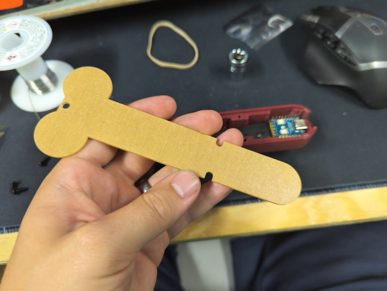
- (1) Printed or Acrylic Backplate
- (1) PCB
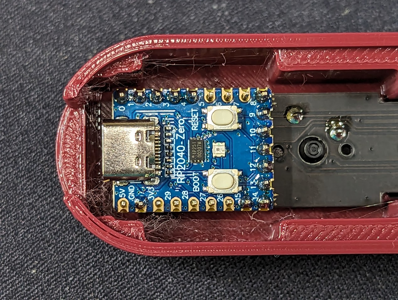
- (1) RP2040-mini with headers
- (3) M3x8mm Button Head Screws
- (2) Encoders with hardware
- (2) Knobs (if included in order)
- (6) Switches (if included in order)
- (6) Keycaps (if included in order)
# Gather Required Materials
You will need everything that comes with the kit as well as a few other items. Those additional items include:
- Soldering iron and solder
- roll of tape
- 10mm socket, wrench or pliers
- rubber band
Now that oyu have everything you need, let's get started!
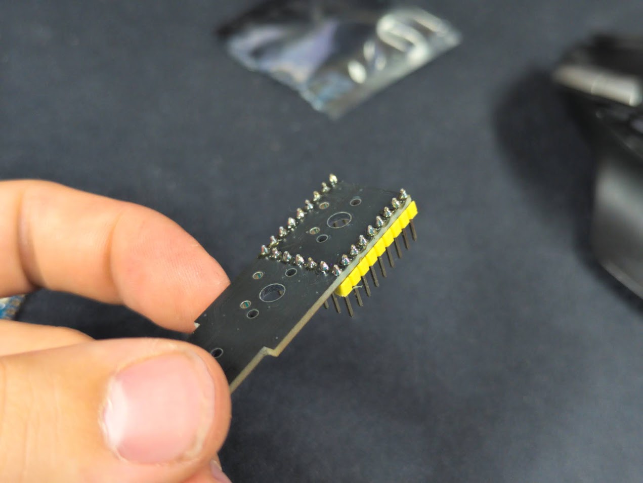
# Solder the Headers
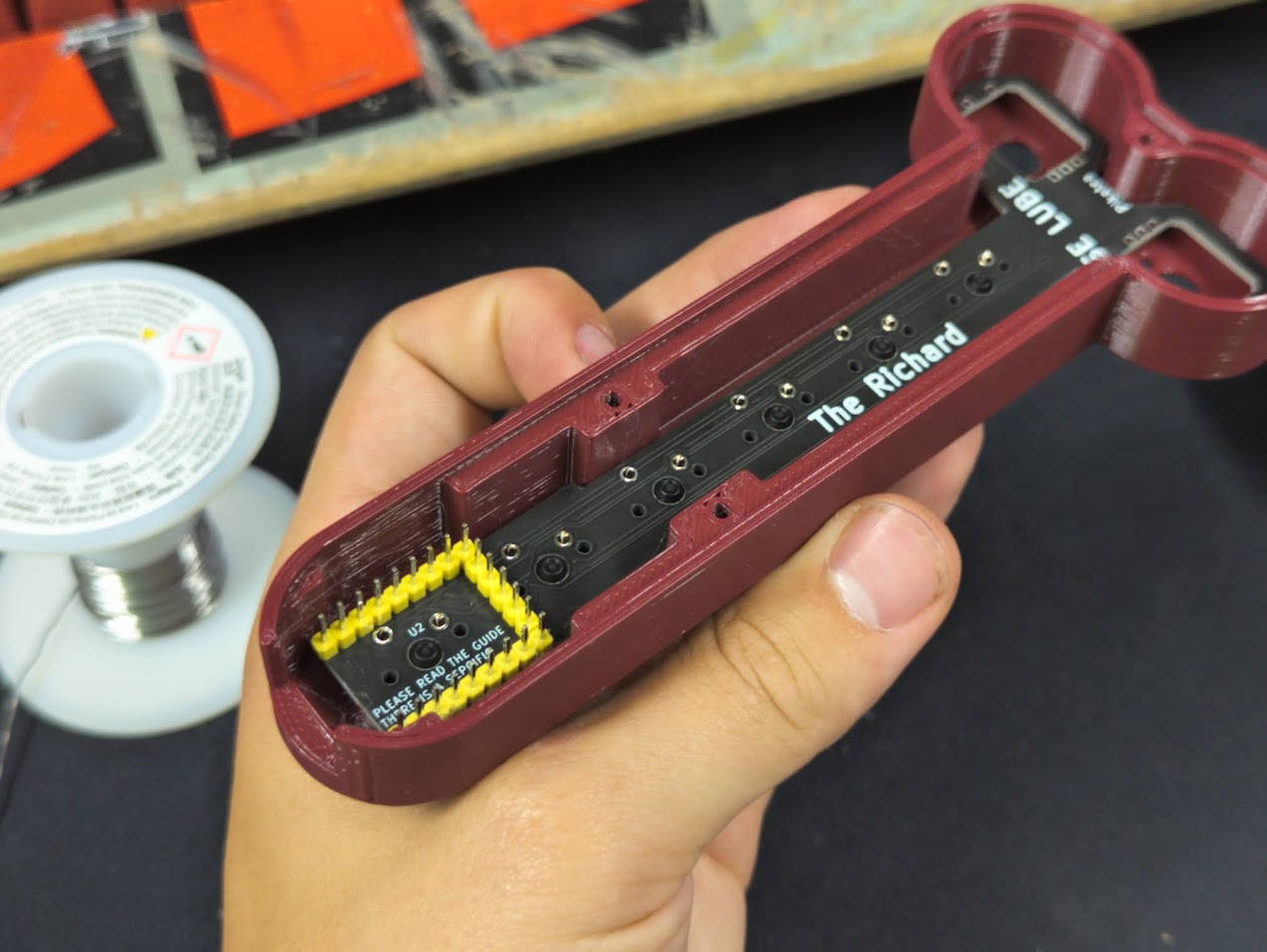
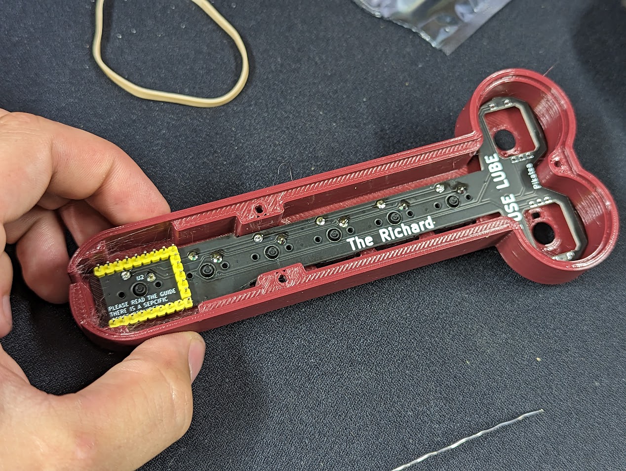
The first step is to solder the headers to the PCB. ONLY the headers.
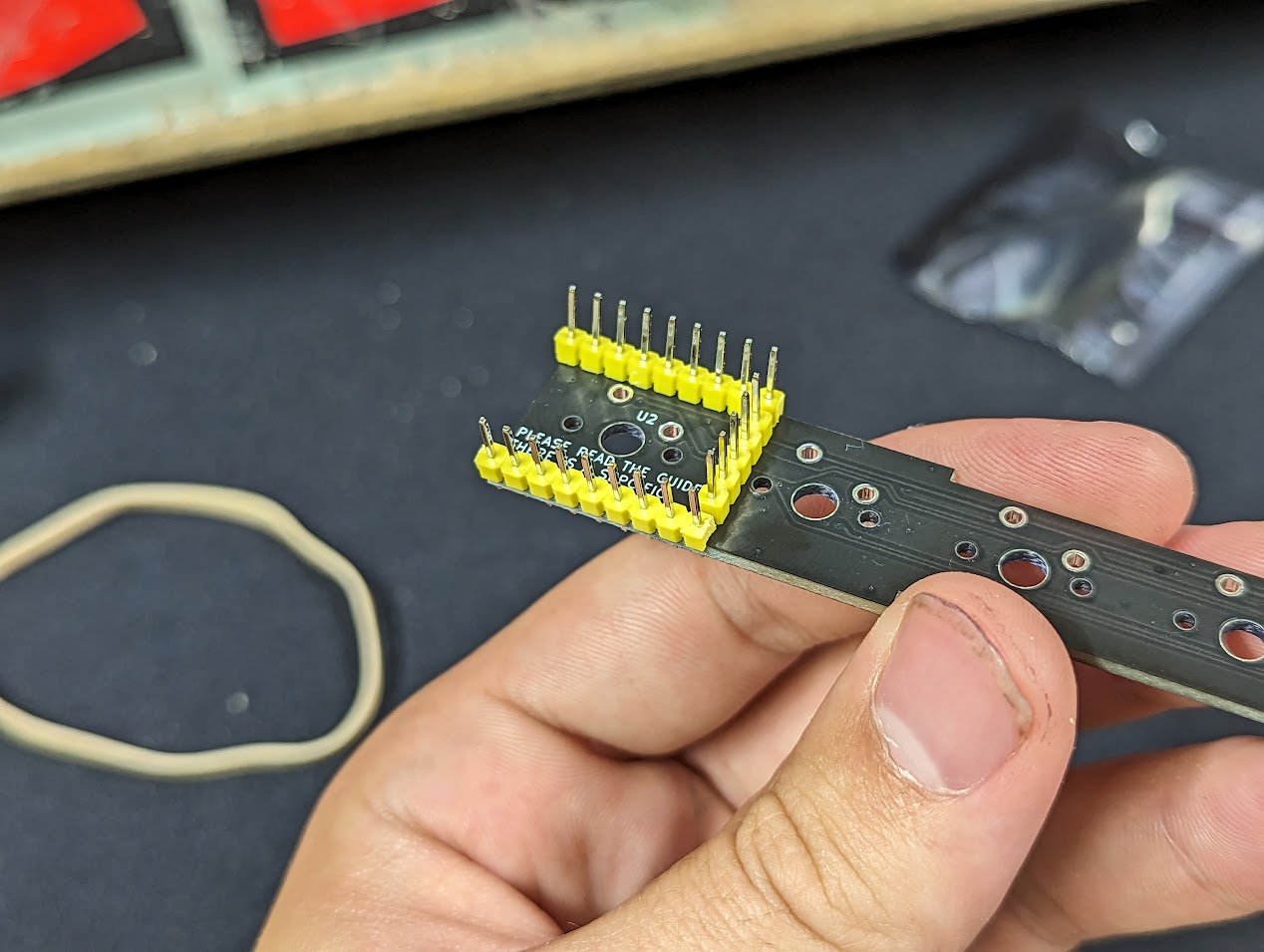
Solder only the headers to the PCB so that you end up with the following. DO NOT SOLDER THE MCU TO THE HEADERS YET
# Install the Switches
Install the switches into the case in the following orientation.

# Solder the Switches
Solder the PCB and headers to the switches. Be careful not to burn the case with the soldering iron. The tip switch will be covered by the MCU so if you ever plan the remove or exchanges these switches, it may be worth while to socket the switch holes. Verify the tip switch is soldered well because you will never have access to it after you add the MCU.
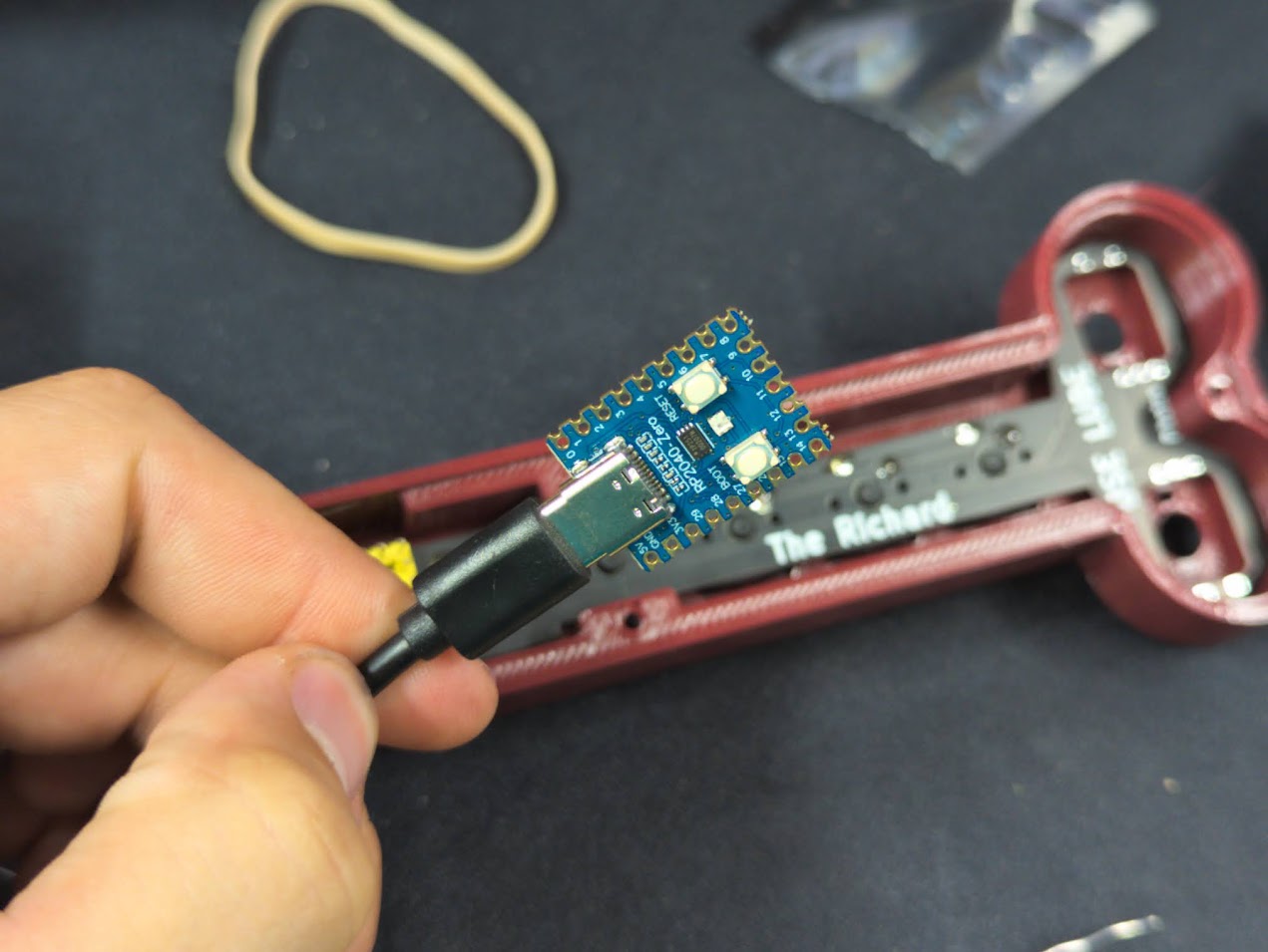
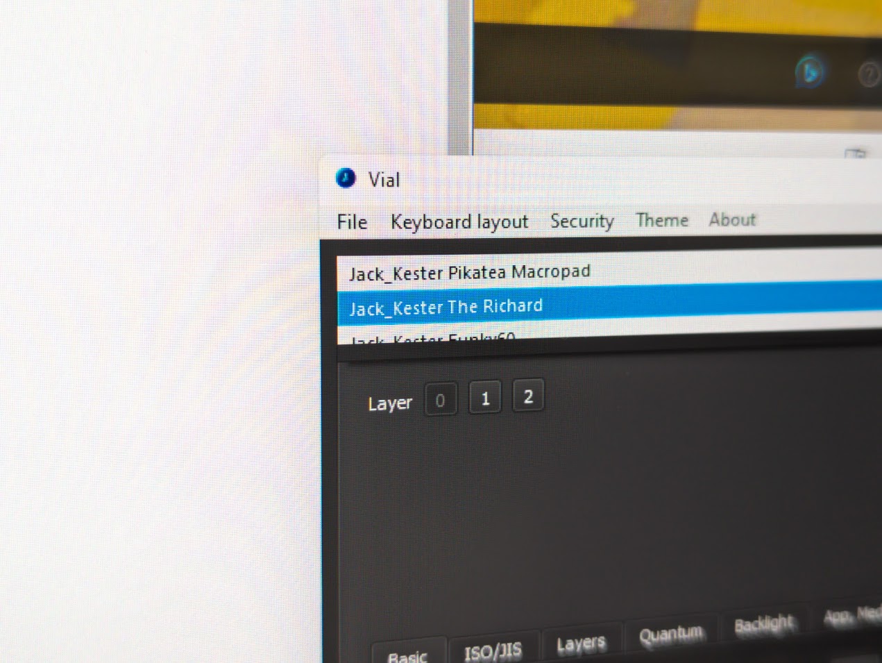
# Test the MCU
Download the latest firmware (opens new window) file (.uf2). Download and install the latest version of Vial from https://get.vial.today (opens new window). While holding the boot button on the MCU, plug it into a computer. There should be a new directory that shows up on the computer. Copy the .uf2 file to this directory. The MCU should automatically disconnect but unplug and re-plug in the MCU anyways. Open Vial and verify that you can see "The Richard Macropad" at the top before continuing. Contact us through support or Discord before continuing if you are encountering issues.
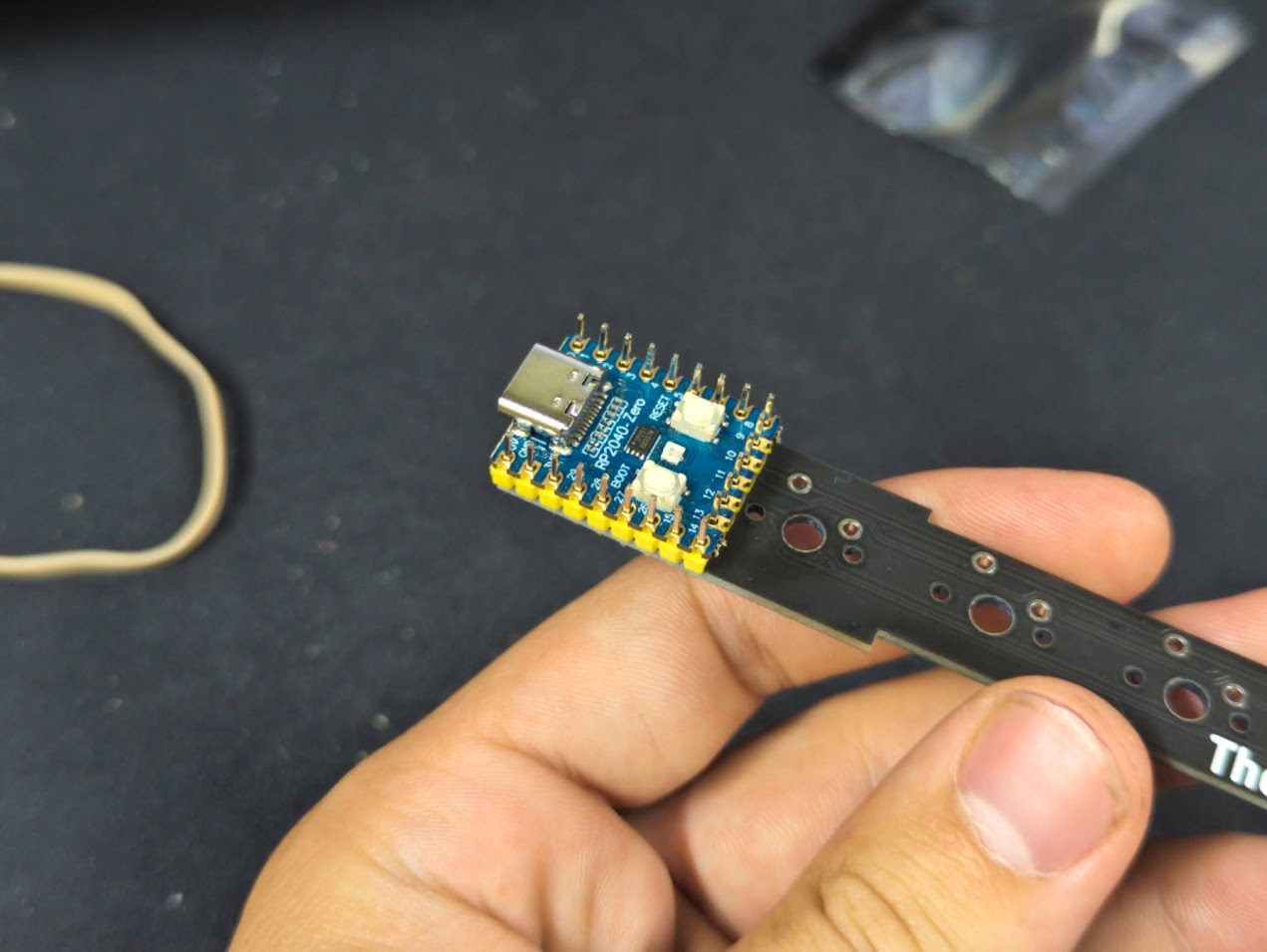
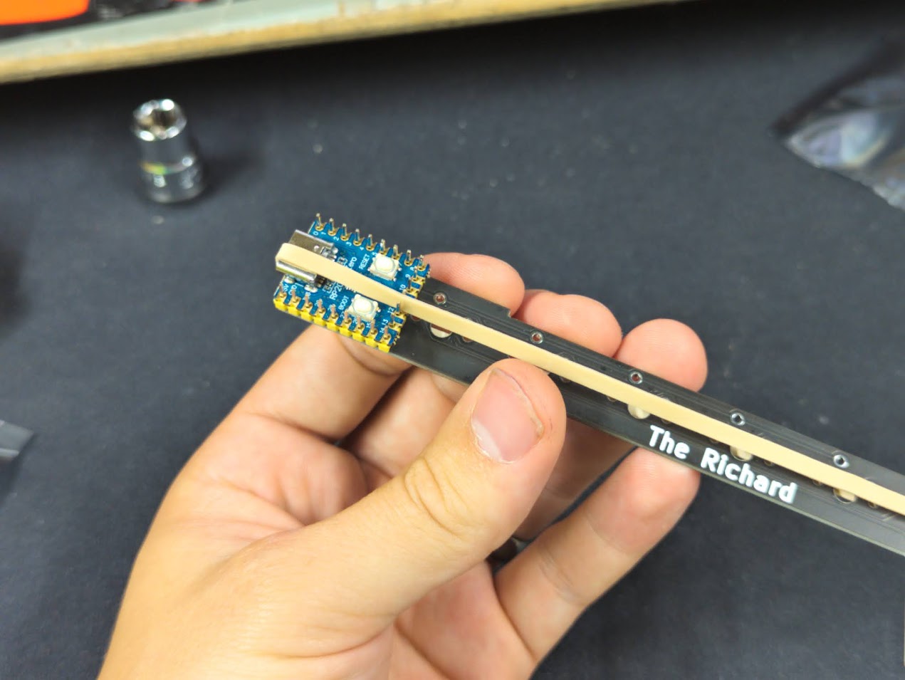
# Solder the MCU
Solder the MCU to the headers as shown below. This is the last of the critical order steps. Solder each pin being careful not to burn the case with your iron.* Flux core solder helps a lot with this.
*you don't actually need to solder each pins. Just the ones in the picture.
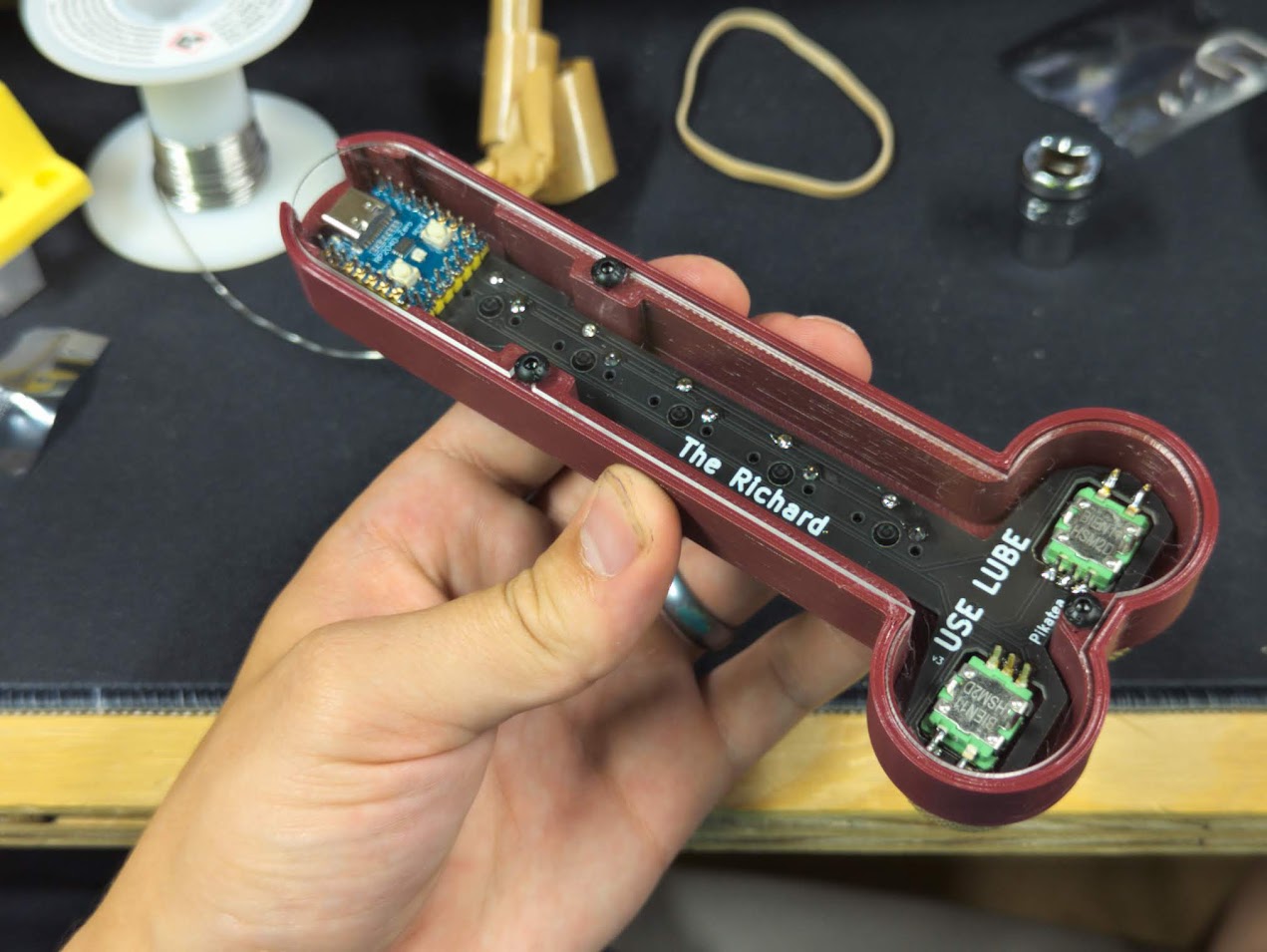
# Install the Rotary Encoders
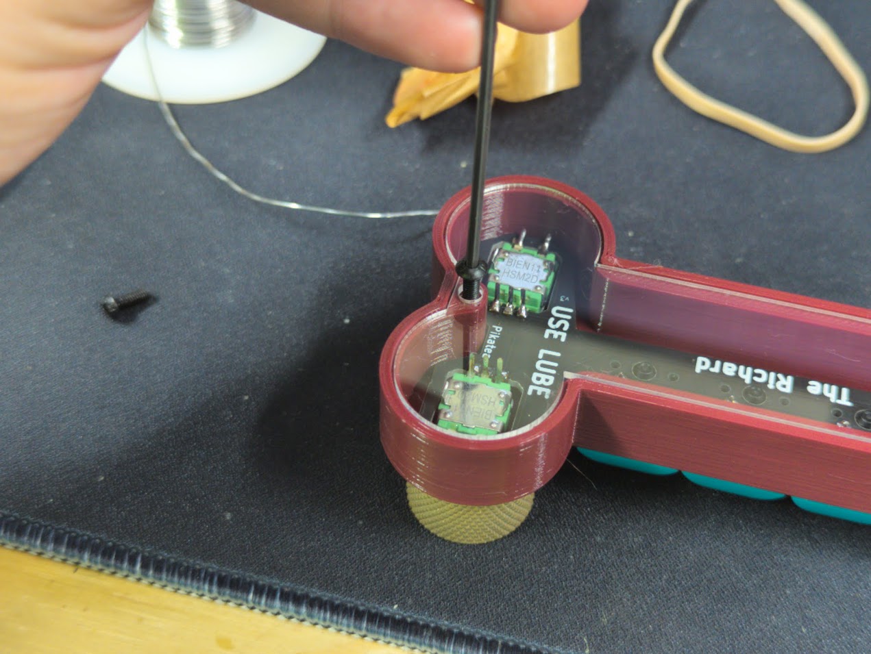
Next up is the rotary encoders. Bend the set of 2 pins slightly as shown. Insert both encoders into the holes with the set of 2 pins facing outwards. hand tighten the washer and nut to hold the encoder in place for soldering. Don't tighten this with any tools just yet. The washer has a slight bend in it so be careful to place the raised part in the center facing towards the front of the macropad.


after the rotary encoder is in place, it is time to solder it. The 2 bent pins on the rotary encoder are resting just above the pads were they need to be soldered to.The 3 shorter pins on the rotary encoder are placed just to the side of the pads were they need to be soldered to. They do not go through the small holes. Take a look at the picture shown from a similar product for a better explanation.


Tighten the encoder with a wrench, pliers or 10mm socket. Do not over tighten. Turning the nut about 1/4 of a full turn after hand tightening should be more than fine.
# Attach the Knobs
Use the Allen wrench included with the kit to bring the set screw inside the knob so that it barely pokes out. Place the knob on the encoder shaft so that the set screw interfaces with the flat part of the encoder shaft. After it is in place, tighten the set screw. Be careful not to over tighten with the 3D printed knobs or it will strip. Error on the side of too loose since it can be tightened later.. Do this for both knobs.


# Add the Keycaps
Add the keycaps to your macropad and click the switches a bunch because it's fun and satisfying.
# Add The Backplate
Install the acrylic or 3D printed backplate using the M3x8mm button head screws. Get each screw started before tightening them down. Error on the side of too loose (the acrylic can crack!).
Add the rubber feet if you'd like. I prefer to go without!
# Done
That's it! You've built The Richard Macropad. Head over to the programming guide for instructions on programming and usage