# FinnGus Keyboard Kit Assembly Guide
Congrats on receiving your FinnGus Keyboard Kit. This guide will walk you through the process of assembling your device! Also, due to the DIY nature of this hobby, as soon as a soldering iron touches or other modifications happen to the board, I am no longer able to issue a refund/replacement. Please refer to the terms and conditions listed on my site for more info.
If you choose to hotswap this with Mil-Max sockets, please see some tips at the bottom of the guide before getting started.
# What's in the Box
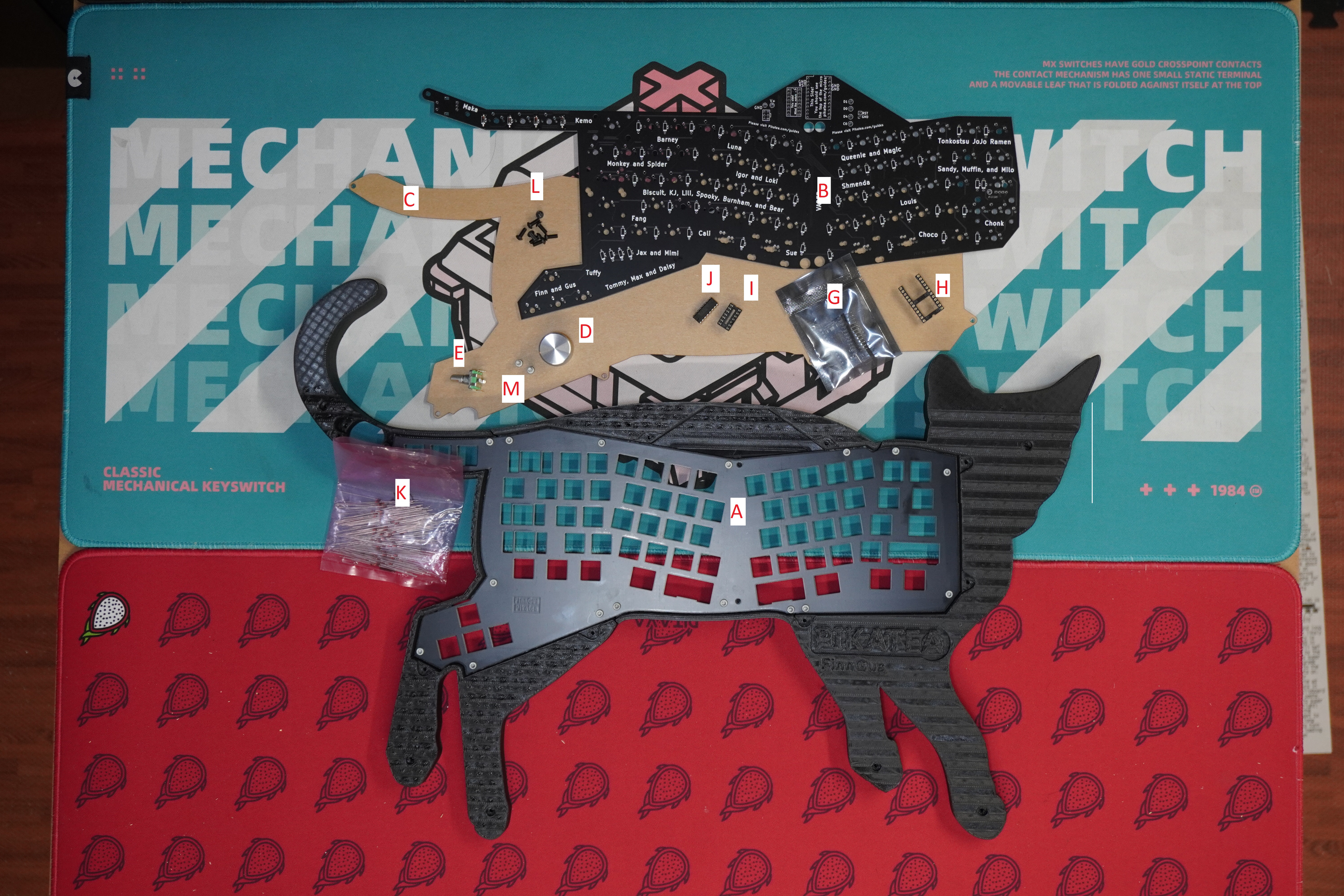
- A - (1) 3D Printed Head
- A - (1) 3D Printed Middle
- A - (1) 3D Printed Tail
- B - (1) Circuit board
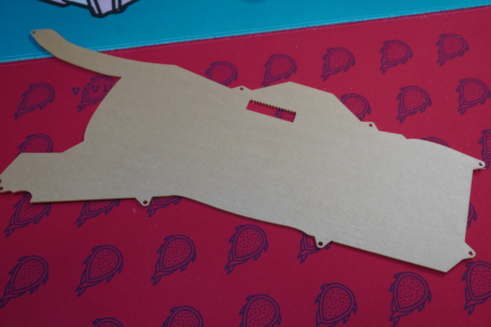
- A - (1) FR4 Top Plate
- C - (1) Clear Acylic Backplate
- -- - (81) Switches (If selected)
- -- - (1) Set of stabilizers (If selected)
- D - (1) Knob
- E - (1) Rotary encoder (no hardware needed)
- F - (1) Allen wrench (1/16th)
- G - (1) Pro Micro
- H - (1) Pro Micro Socket
- I - (1) I/O Chip
- J - (1) I/O Chip Socket
- K - (75) Diodes
- L - (8) M3x8mm button head socket heads
- M - (2) M3x6mm socket head screws
- A - (12) M3x6mm socket head screws (already installed in case)
Please double check everything is here! There is a small chance we forgot something or that your order is wrong; in the case this is true, please reach out via email at support@pikatea.com and we will work with you to get it right.
# Gather Required Materials
You will need everything that comes with the kit as well as a few other items. Those additional items include:
- USB-C cable
- Soldering iron and solder
- Philips head screw driver
- Allen wrenches (1.5mm (included) and 2.5mm)
- Flush cut snips
- About 3-4 hours time
Now that you have everything you need, lets get started!
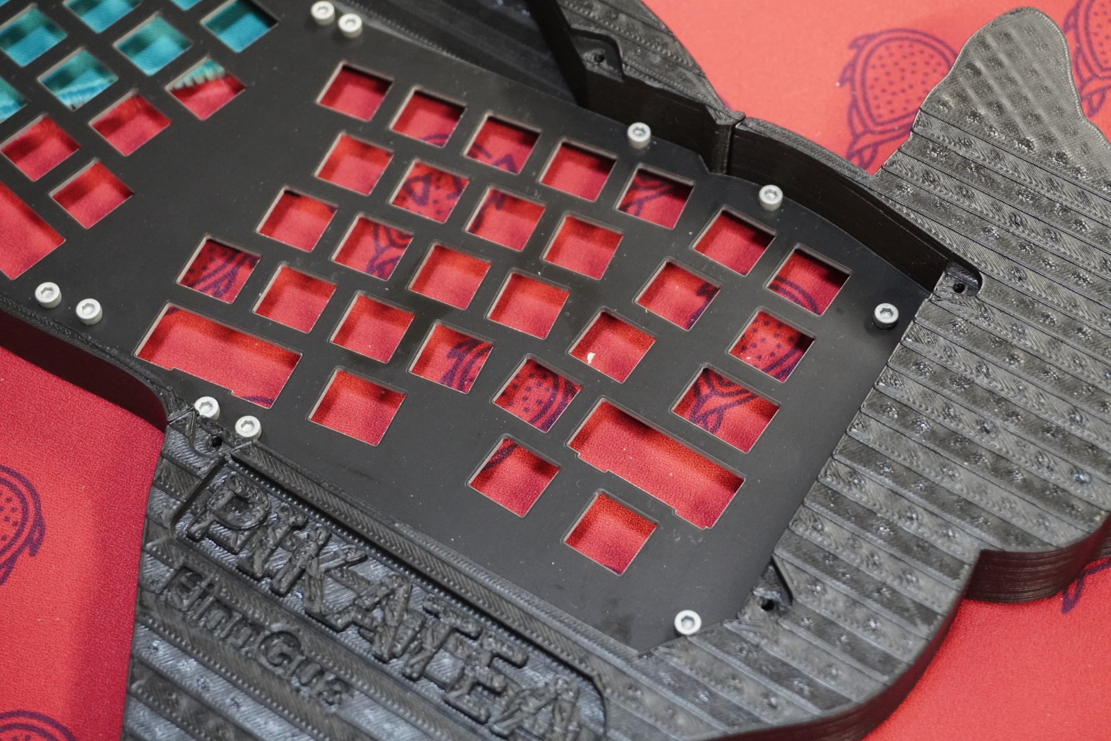
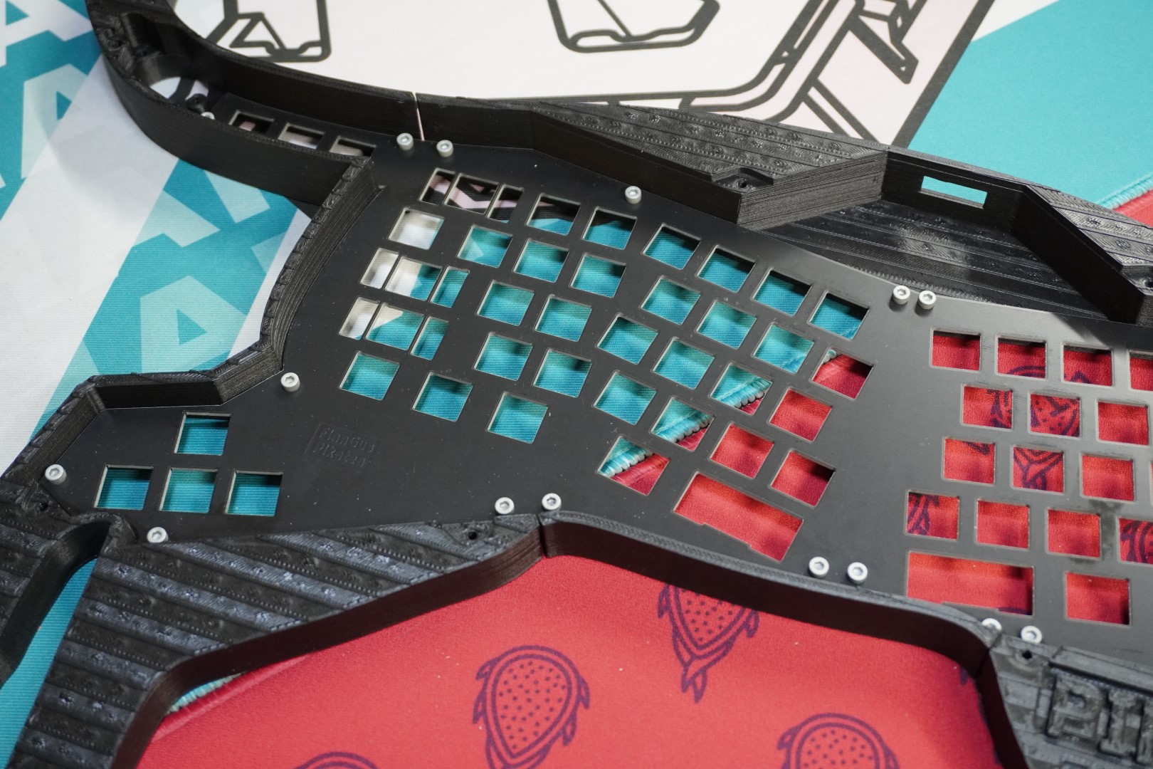
# Combine Case Sections
The case is divided into 3 sections which are attached together with the top plate. We plan on completing this step for you but you may have to finish it.
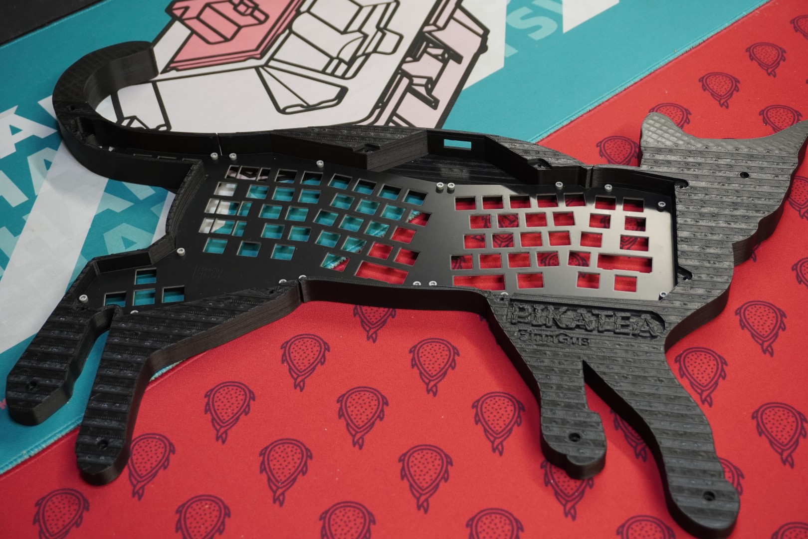
Use the M3x6mm socket head screws to attach the top plate to each of the 3 case sections. You will be creating/cutting the threads into the plastic. Be sure not to apply too much pressure otherwise you might strip the threads you are creating. Start with the 2 holes close to each other in the center-top and center-bottom of the board (belly and back). This way, if you do strip the hole, it is not an issue since another hole is right next to it. Use this to practice and get a feeling for the correct amount of tension.
 With the case section assembled, set it aside for now.
# Prepare The PCB
The PCB is the most complicated part so we've broken it down into 6 partial steps. Please pay special attention to the details on these steps. I'd recommend reading through this entire section before getting started. It's important to be as carefuly as possible to not scratch the PCB and damage it. Take your time!
- Flash The Firmware
- Solder In The I/O Chip and Pro Micro
- Solder in the Diodes
- Solder In The Encoder
- Screw In The Stabilizers
- Verify And Test
# 1. Flash The Firmware
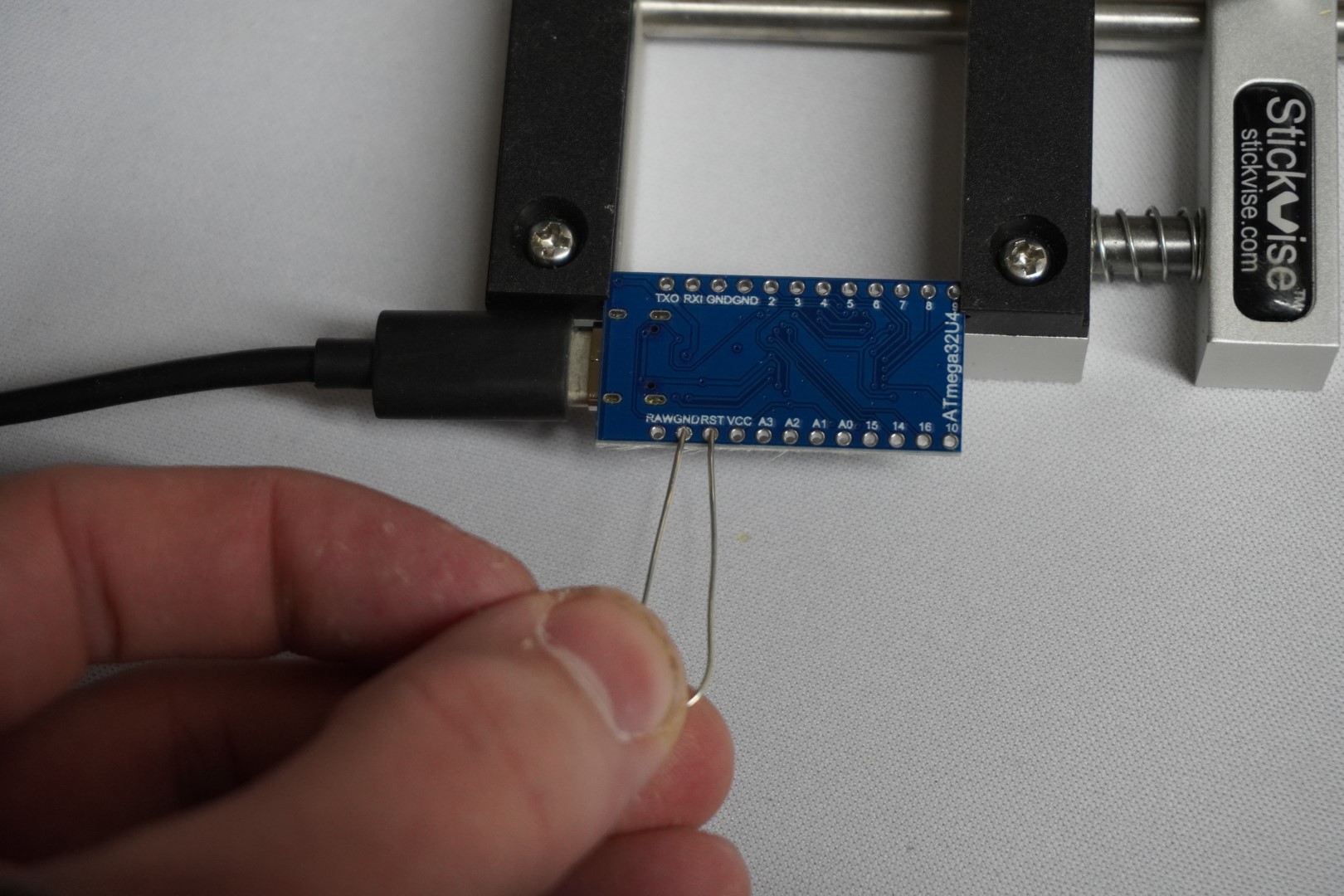
Let's start with flashing the firmware onto the included Pro Micro to make sure that is working. Plug it into your computer using a USB-C cable.
We already have a generic guide for flashing firmware which is here. Follow that guide and use the FinnGus firmware which can be downloaded from that page. Since there is no reset button on the Pro Micro, reset the device by connecting the pins RESET and GND with a metal object (a bent paper clip works well). Download and install Vial (opens new window) and make sure your computer recognizes the device as a FinnGus before moving on.
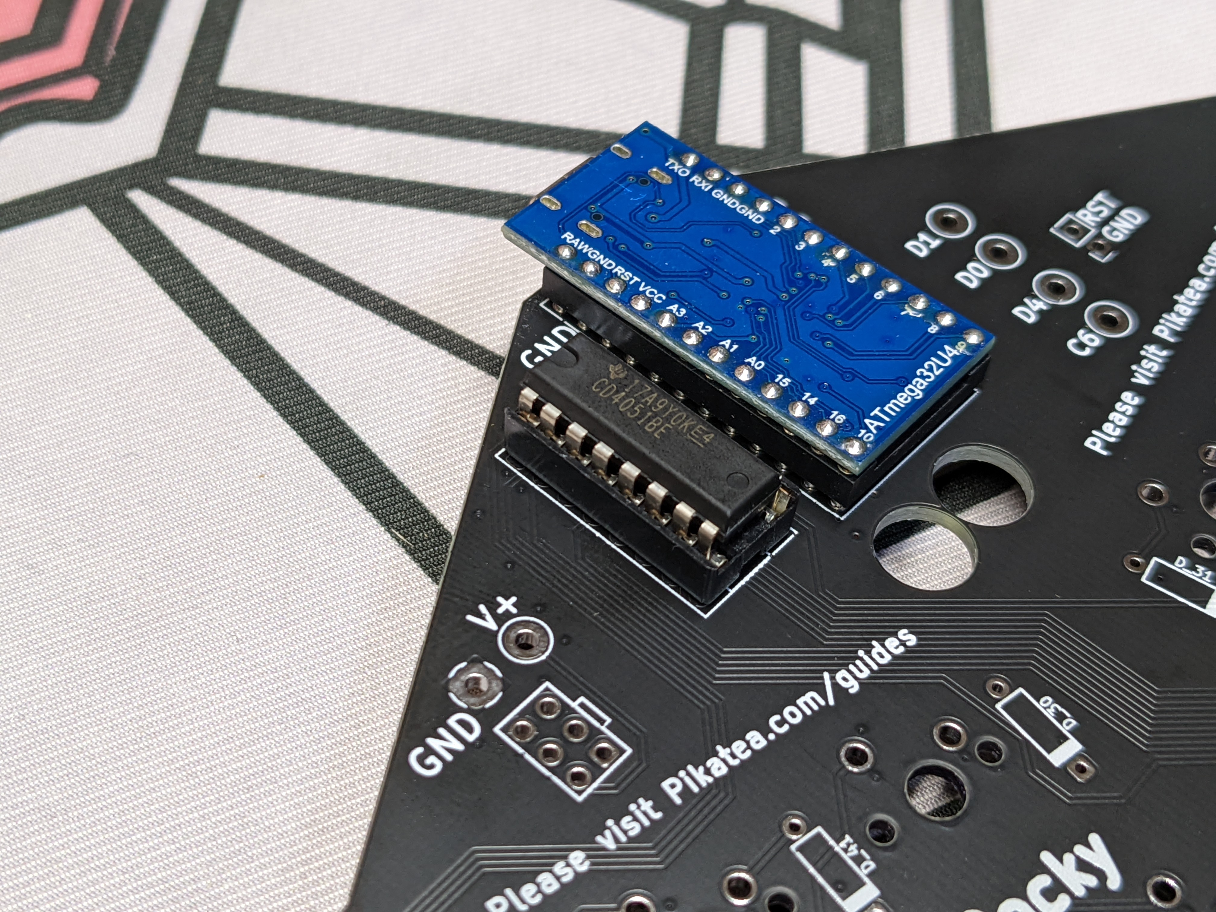
# 2. Solder In The I/O Chip And Pro Micro
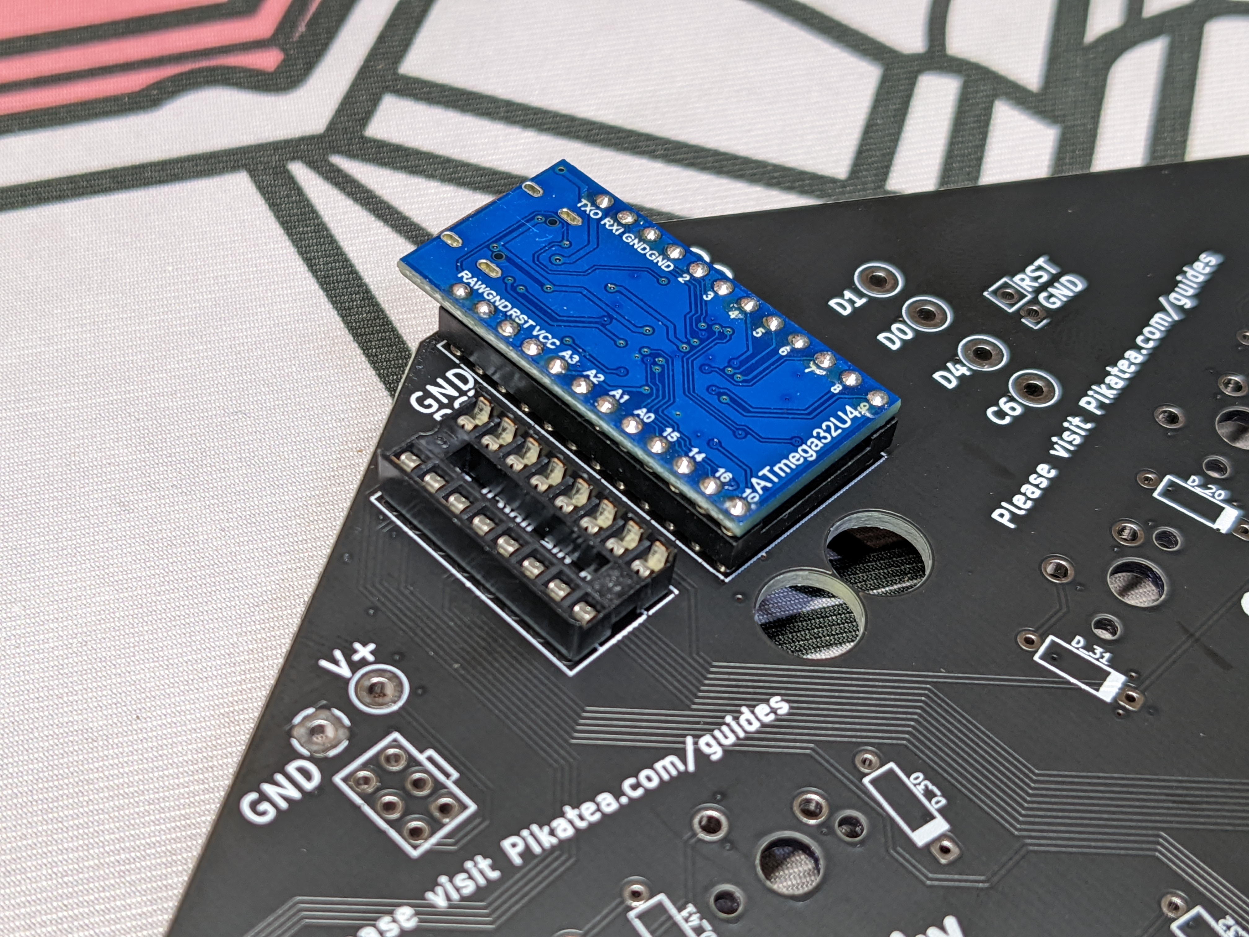
The kit includes a socket for both the Pro Micro and the I/O expansion chip.
Prepare the Pro Micro socket by cutting one of the connecting bits of plastic so the USB port does not interfere with it. DO NOT USE FLUSH CUTS. Use a hacksaw. The plastic is brittle and breaks easily. Because of this, we have already completed this step for you. 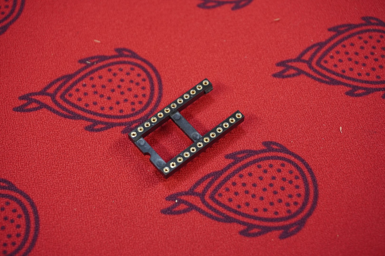
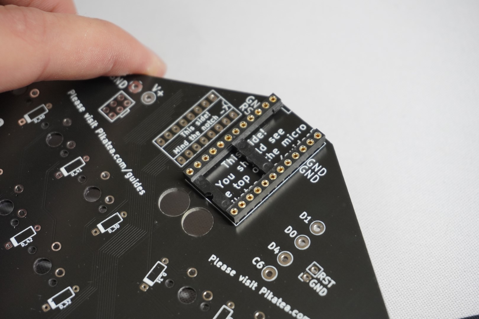
Place the Pro Micro socket into the PCB like shown and solder it into place. Be sure the socket is flush. Start with a corner, and verify. Solder the other corner and verify again. Finally, solder the rest of the pins.
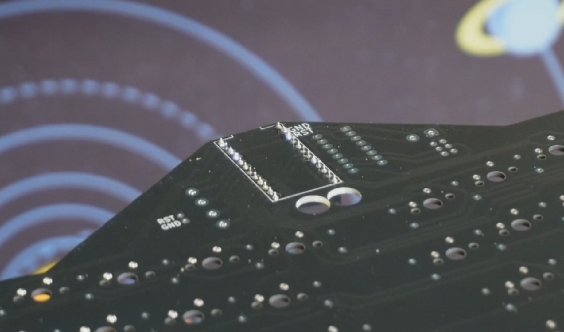
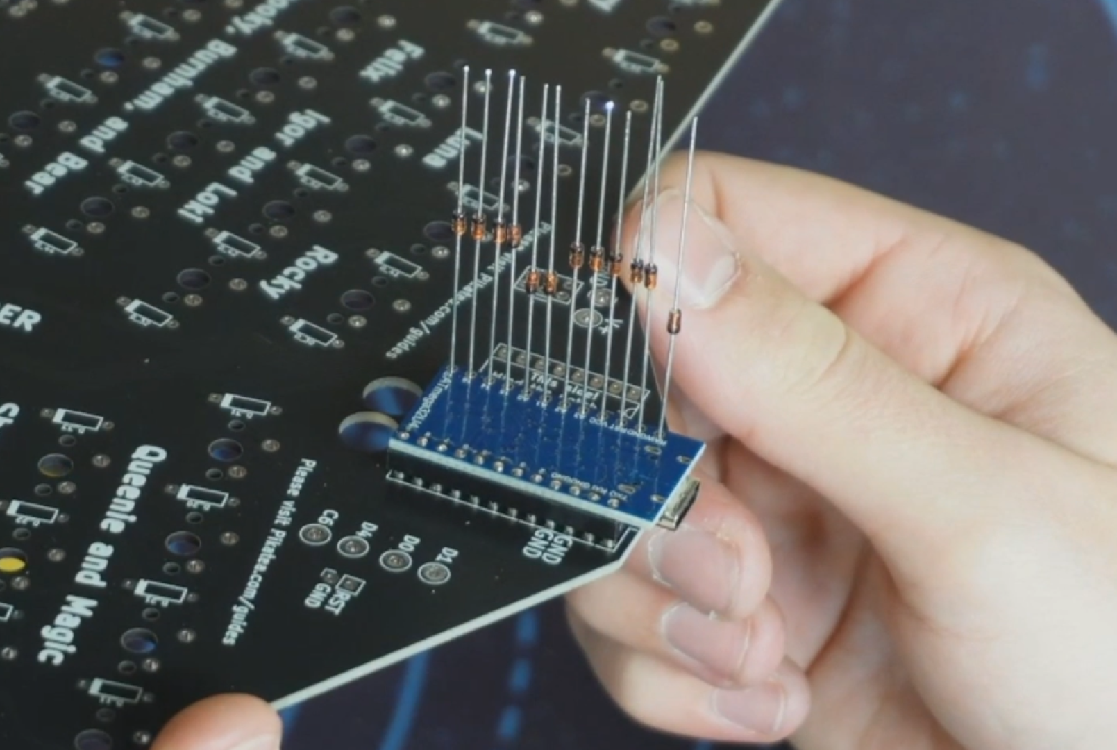
Place the Pro Micro UPSIDE DOWN with the components facing away from you. Insert legs from the included diodes into each hole and use flush cuts to snip the excess off. Finally solder the cut diodes legs to the Pro Micro.
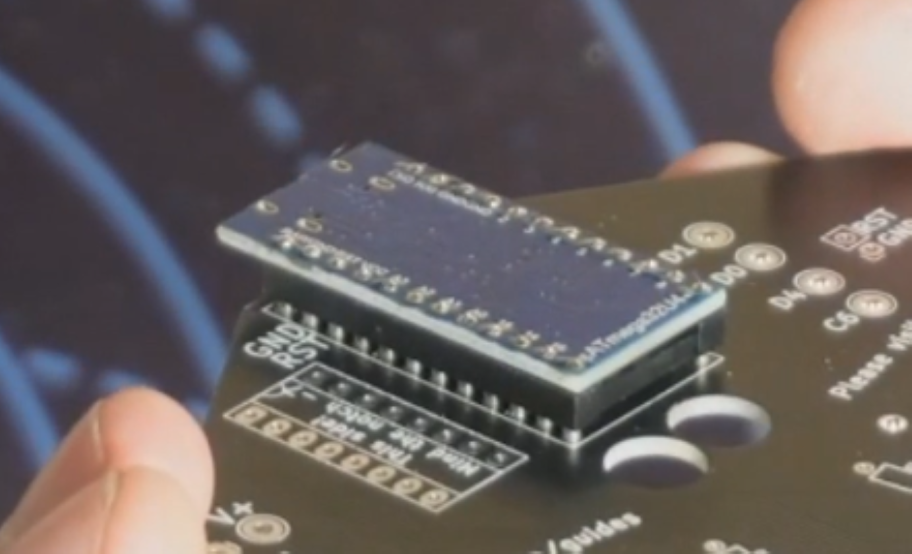
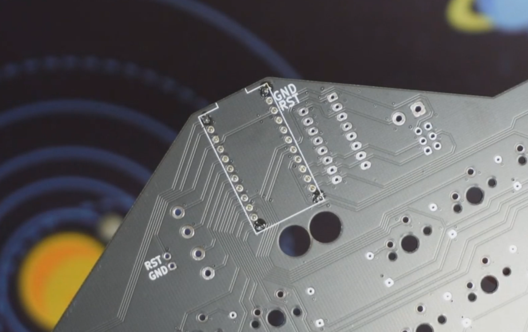
Place the DIP socket into the PCB like shown and solder it into place. Like the Pro Micro socket, make sure it is flush.
Insert the I/O expansion chip into the DIP socket. Pay special attention to the orientation. The indent/mark should be facing towards the north part of the board.
# 3. Solder In The Diodes
- Bend the diode and insert it into the PCB being careful it is the correct orientation. The black bar on the diode matches with the thicker white bar on the PCB.
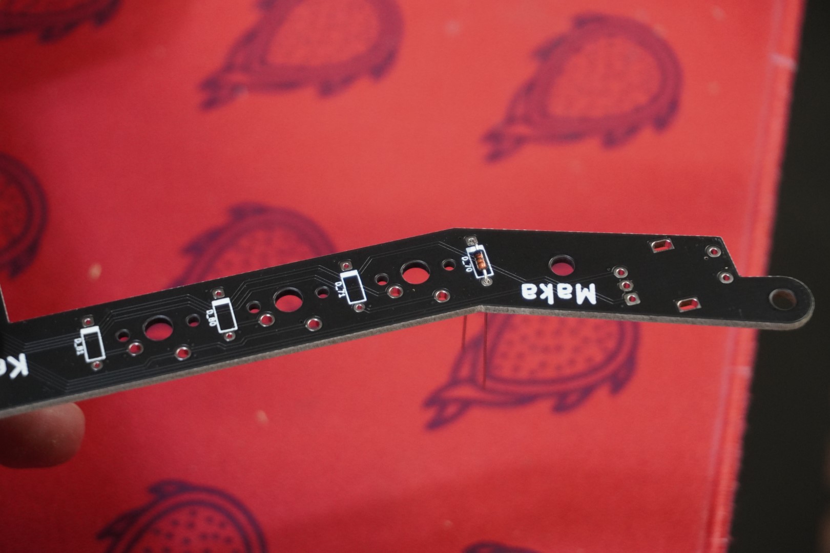
- After the diode is inserted, bend the leads outwards so it stays in place. Repeat steps 1 and 2 for each diode.
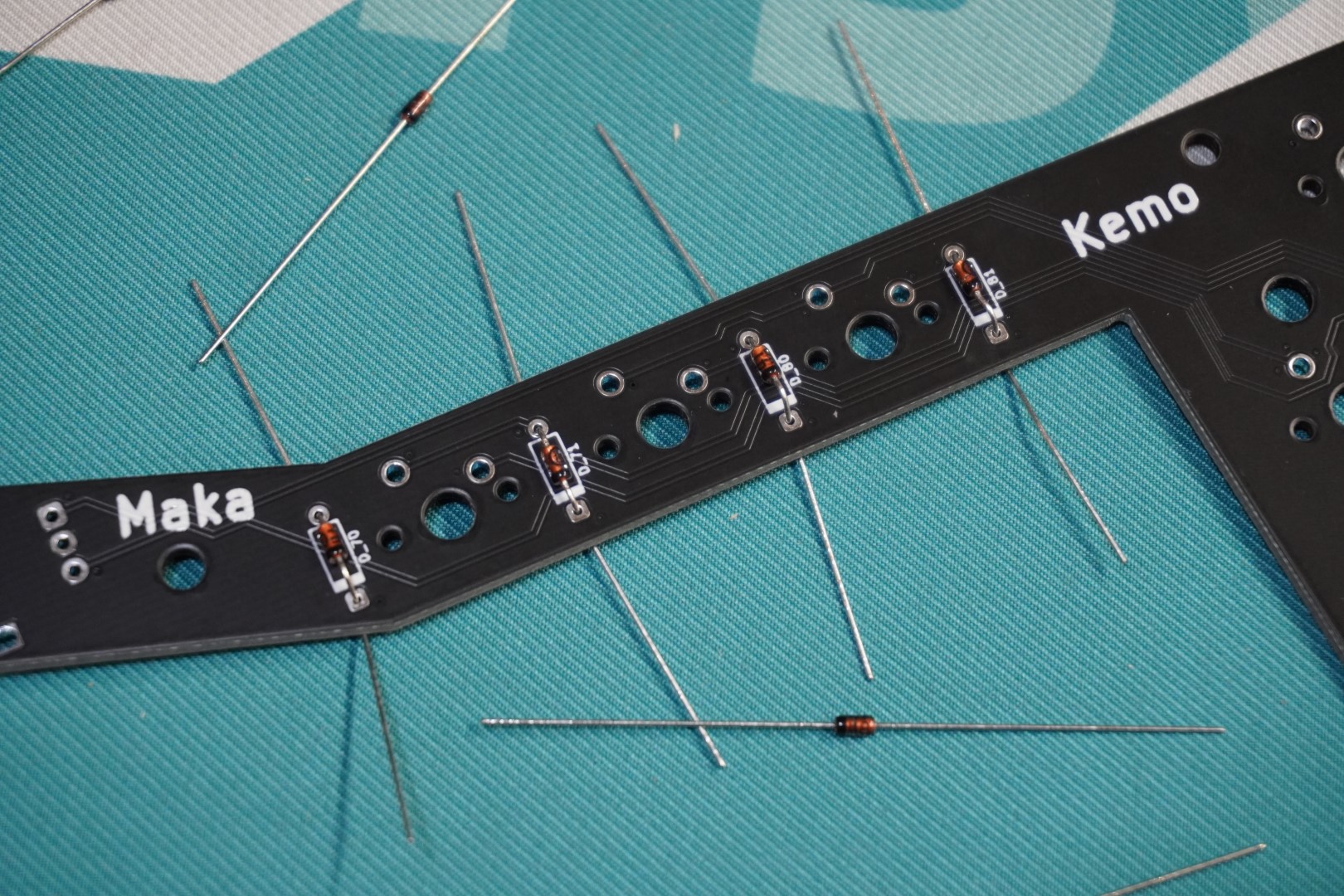
- Finally after each diode has been inserted, solder each one. 
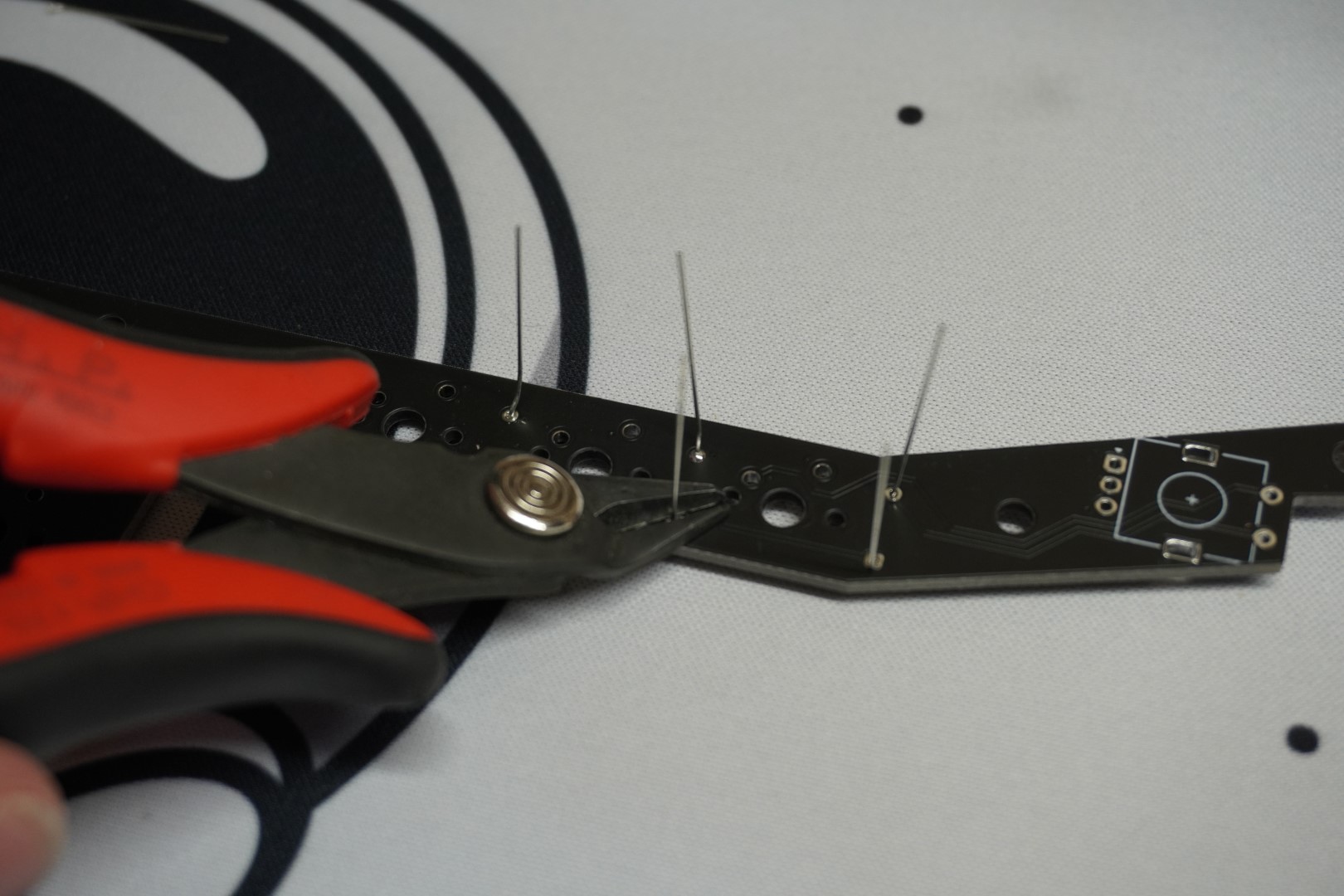
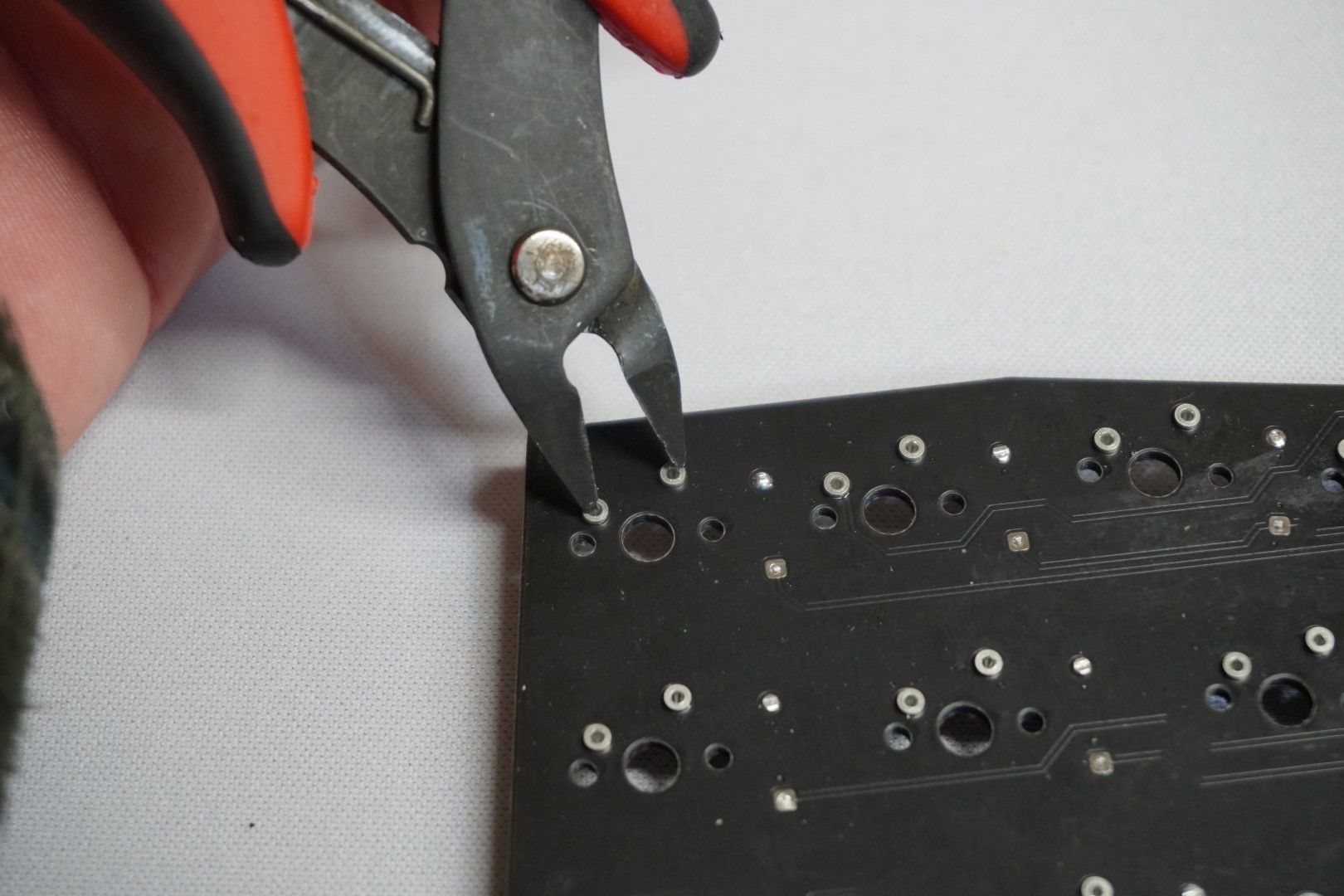
- Bend the diodes legs straight and use flush cuts to them off. Be careful not to scratch the PCB when doing this.
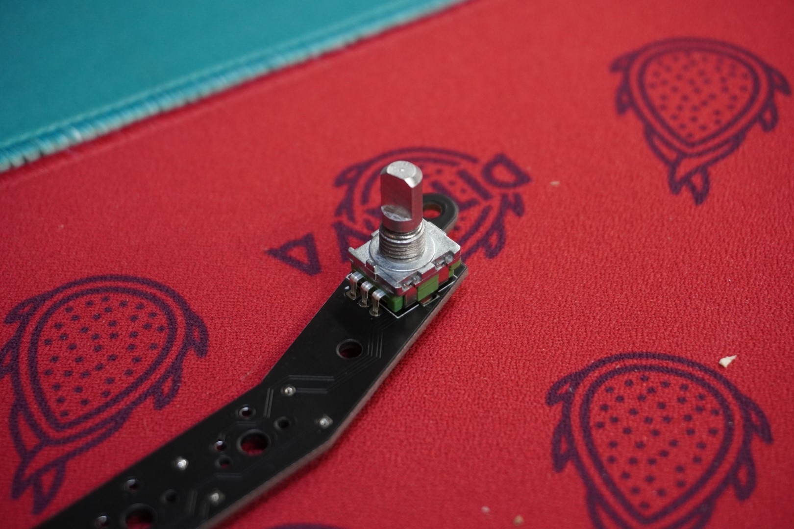
# 4. Solder In The Encoder
Flip the PCB to the front side facing you. Insert the rotary encoder into the footprint as shown. Make sure the encoder is as perpendicular as possible before soldering the connections. It might help to use a box or the edge of a table.
# 5. Screw In The Stabilizers
Install the PCB mounted stabilizers. They usually screw in but some might clip in. Below are a few links that explain keyboard stabilizers and how to install them.
# 6. Verify And Test
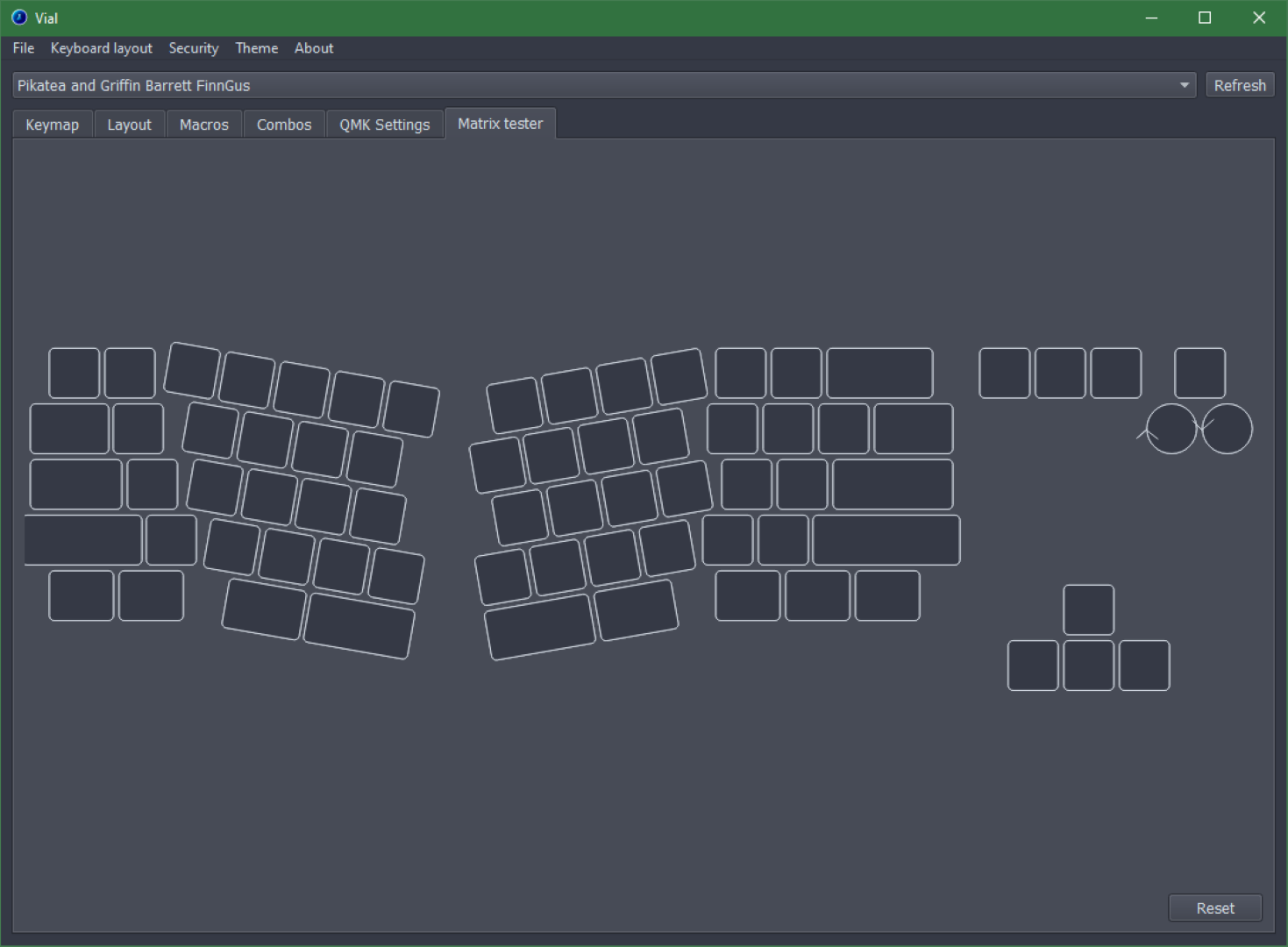
While not strickly necessary, I like to test the PCB at this point before I solder in the switches. It's much easier to fix issues now if they come up.
Plug in the PCB. Open Vial and select the keyboard in the top drop down menu. From there, select the Matrix Tester tab. This will show you every keypress. Test each key by using a metal object and connecting the switch pads together.
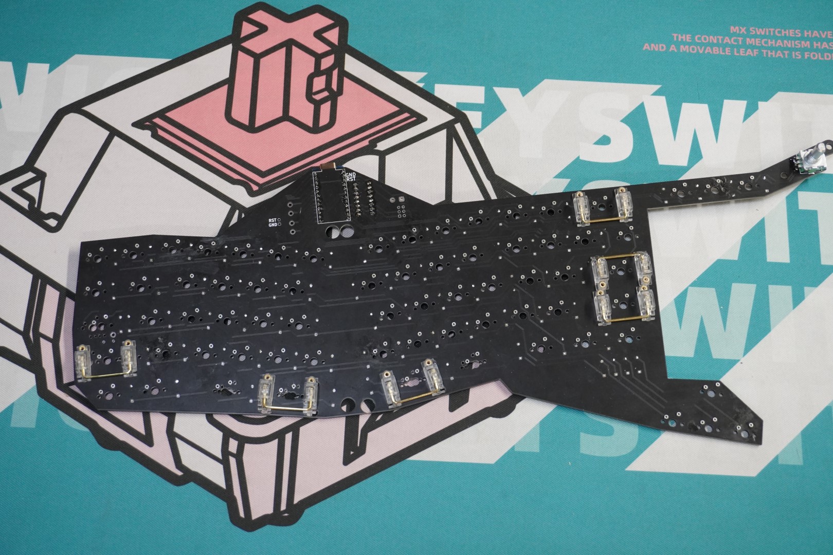
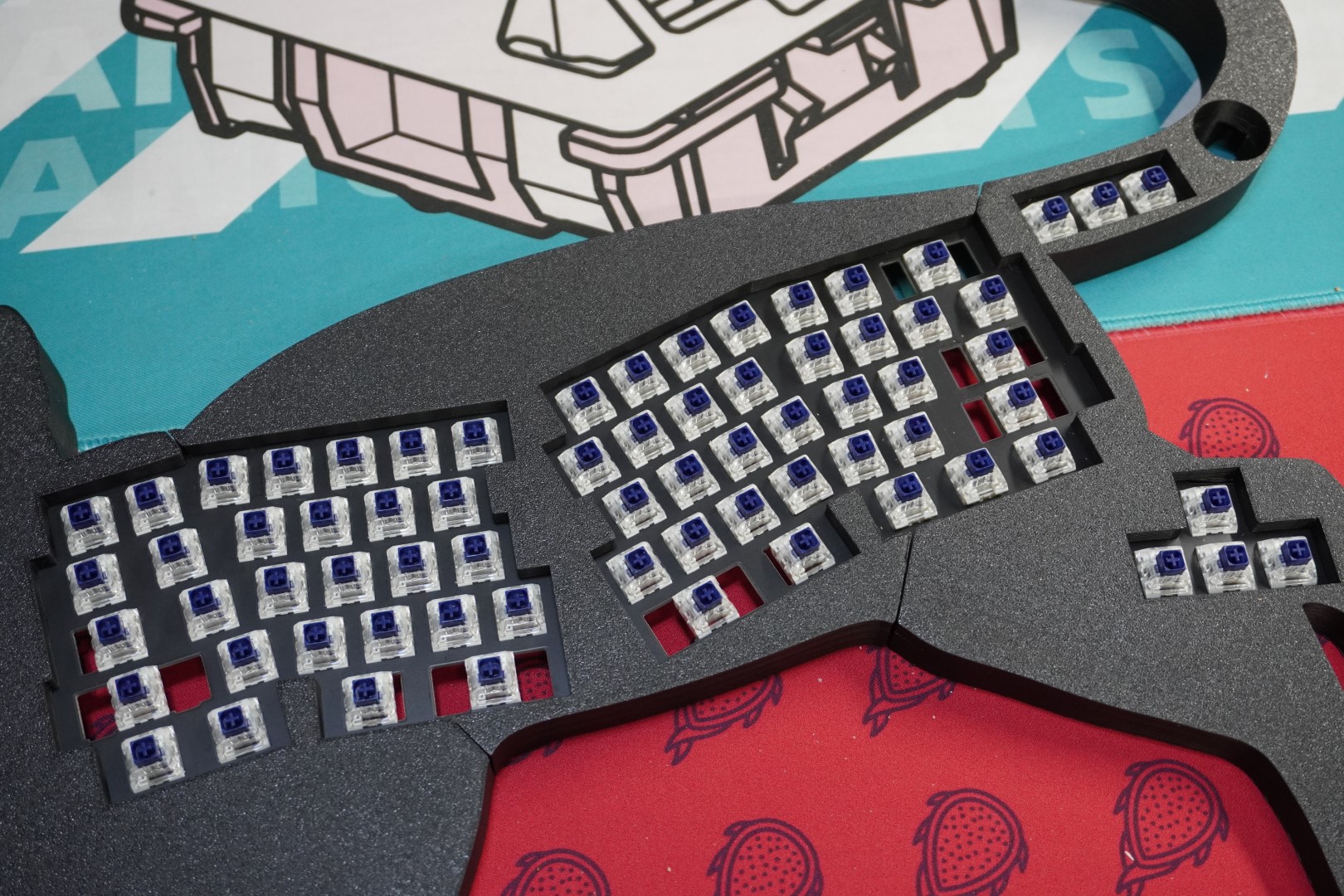
# Install The Switches Into The Top Plate
Insert the switches you'd like to use with the LEDs facing south
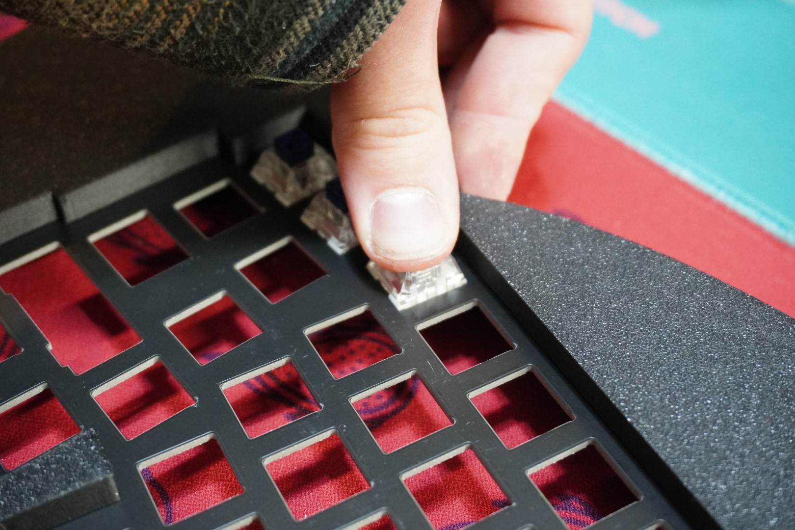
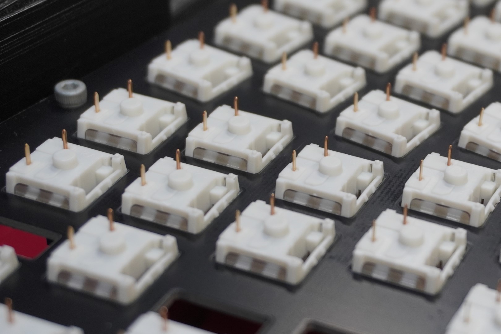
 Check that all the pins are not bent and facing straight up.
 Make sure they line up with the layout you'd like to use. Dry fit the PCB to make sure everything lines up/works. Be as careful as possible to not scratch the PCB with the switch leads.
# Solder 1/2 Of The Corner Switches
The next step is to solder the PCB to the switches but it's recommended to do it in a particular way.
Start with 1 switch in the "corners" of the PCB. Solder only 1 lead (1 out of 2). The goal is to ensure the PCB is siting up against the back of each switch before moving on.
Use a large box (we recommend the box the kit came in) to help support the device and allow the enocder to not interfere.
(as you can see, we don't have pictures of this process. If you'd like to take a few pictures to help improve the guide that would be amazing!)
# Solder The Switches
After the PCB is in place and up against the switches, solder the rest of the switches. I like to solder half of each switch first and then come back and finish each switch.
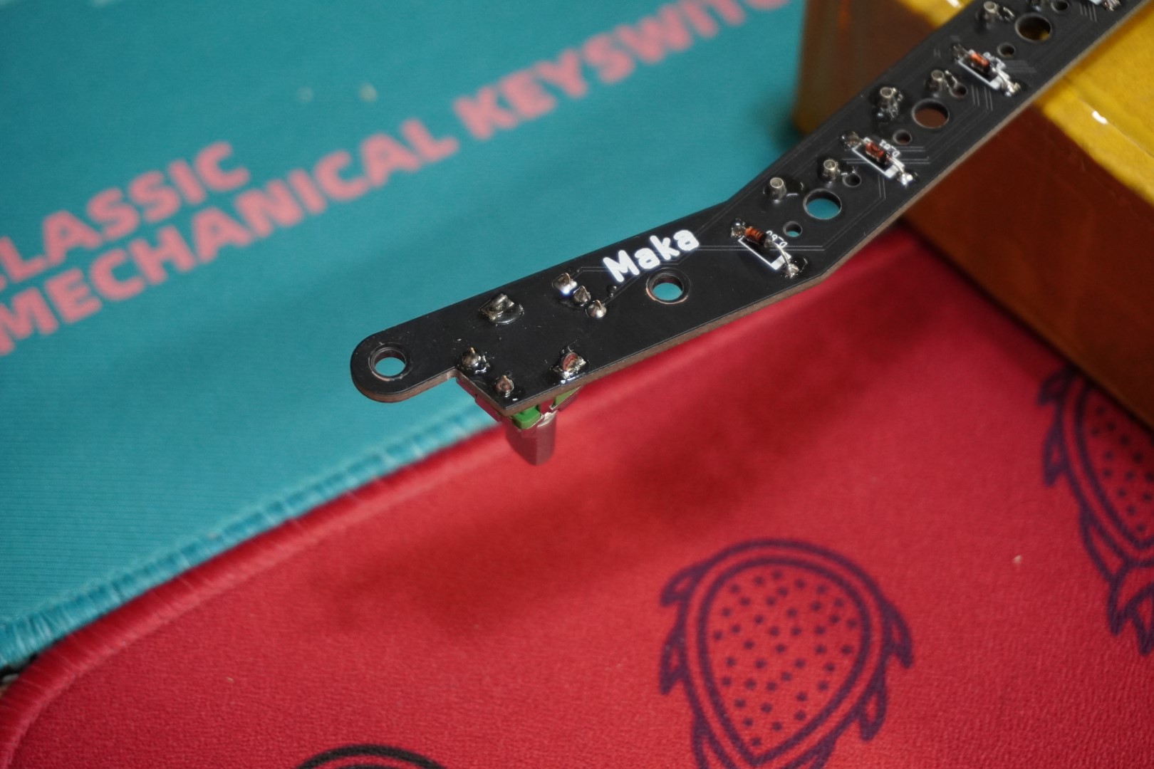
# Reinforce The Encoder
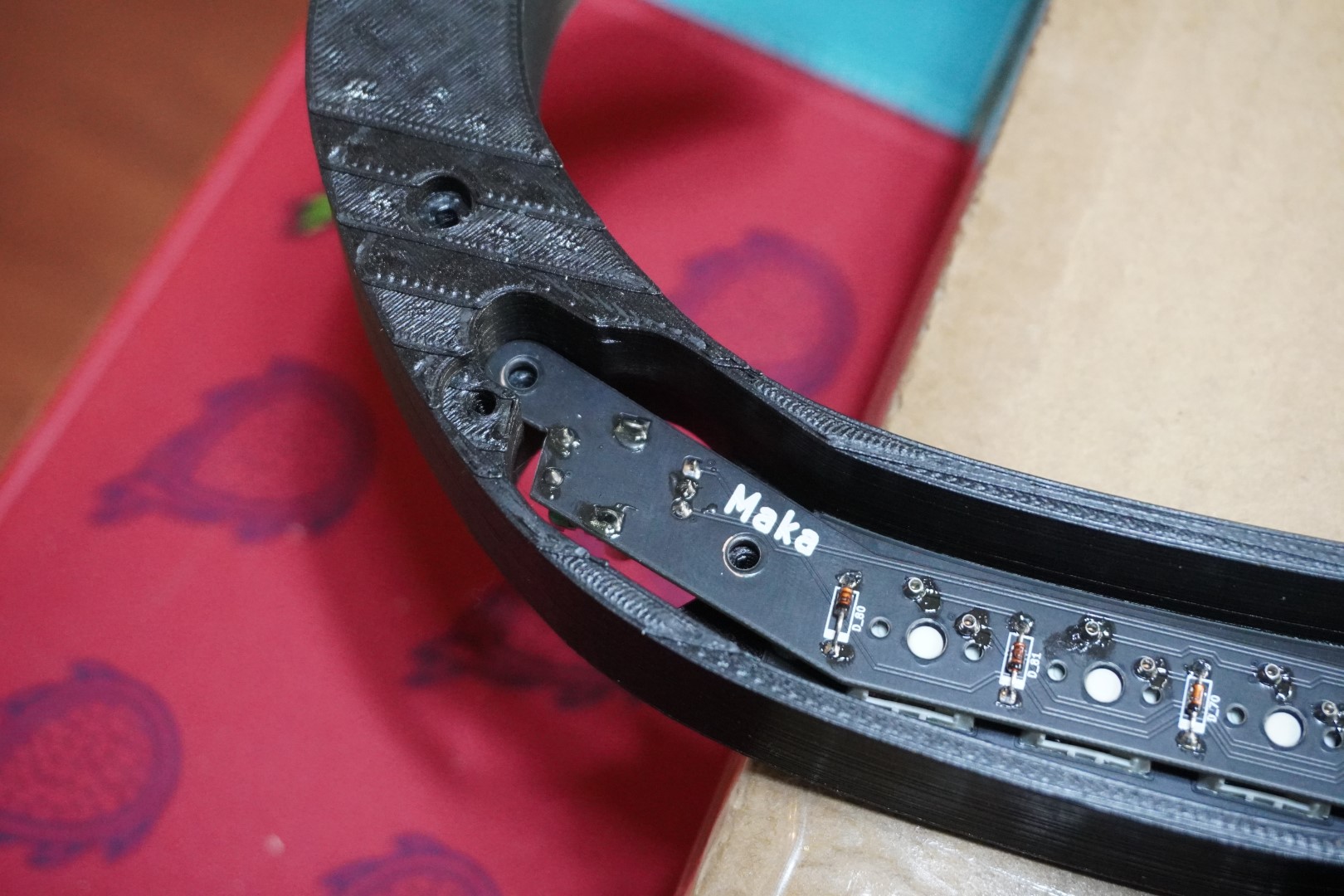
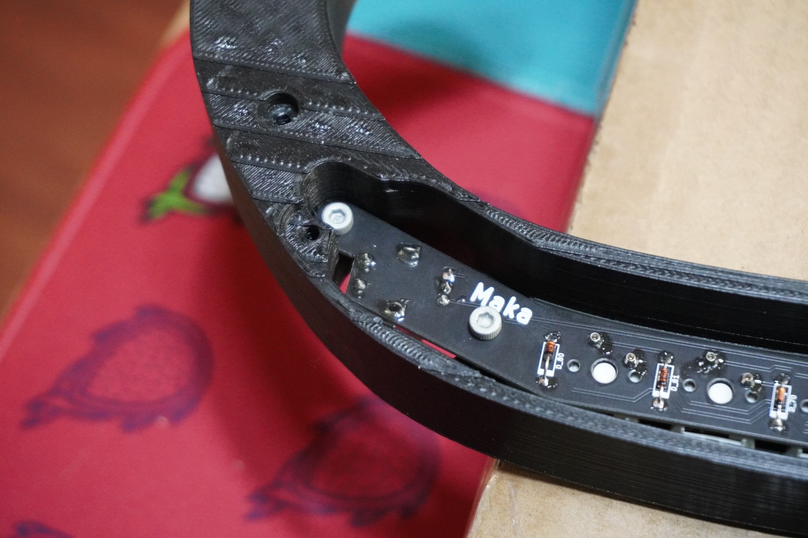
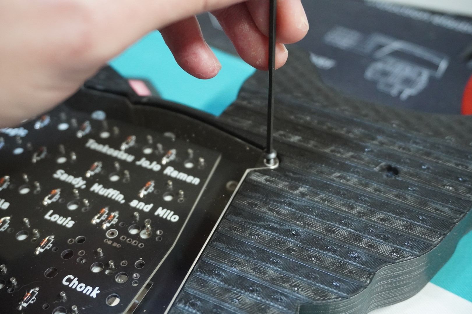
The encoder is not plate mounted so that section of the PCB has to be supported. Use the included M3x6mm socket head screws and screw the PCB to the case near the encoder as shown below. Use a large box (we recommend the box the kit came in) to help support the device and allow the enocder to not interfere.
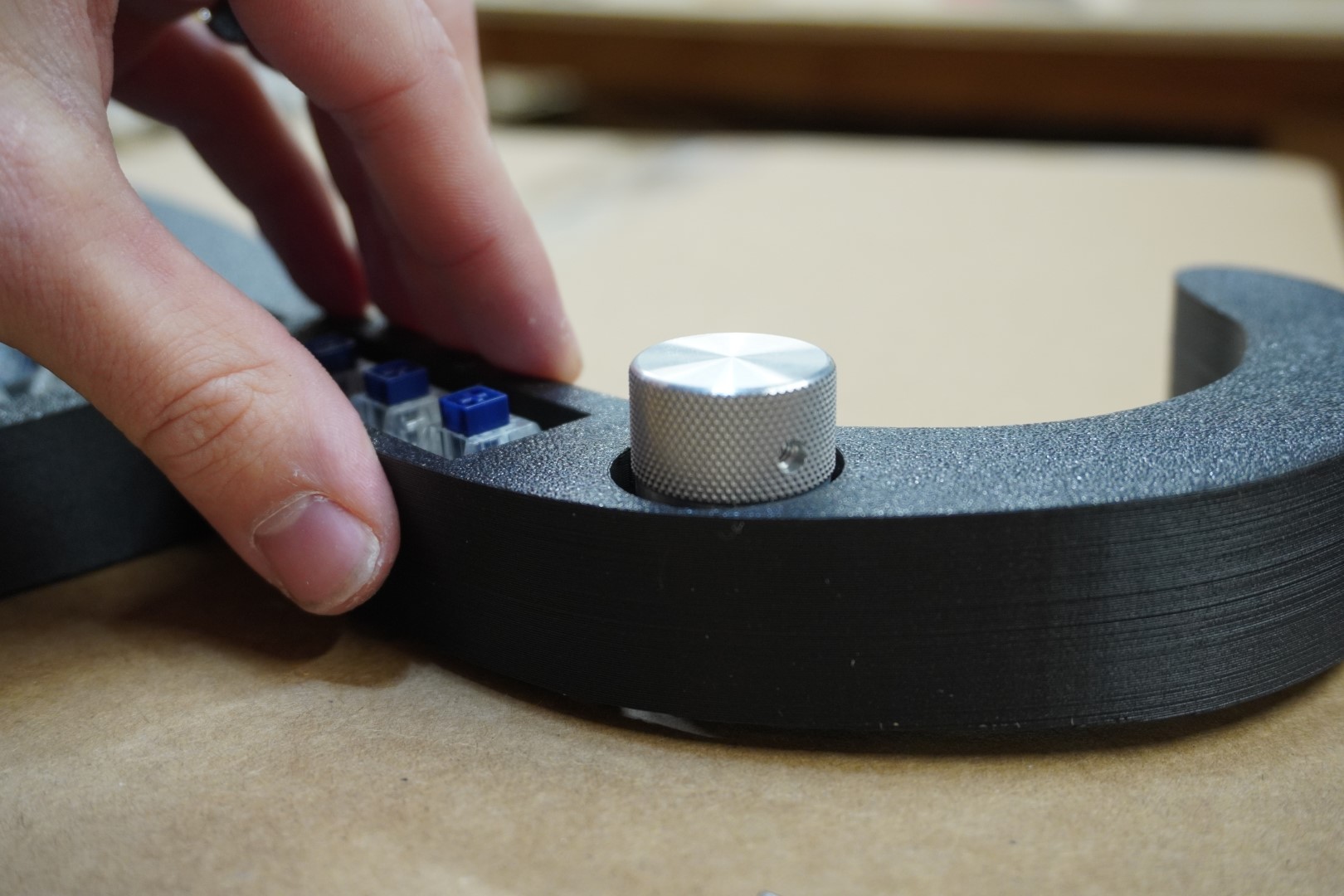
# Attach Knob
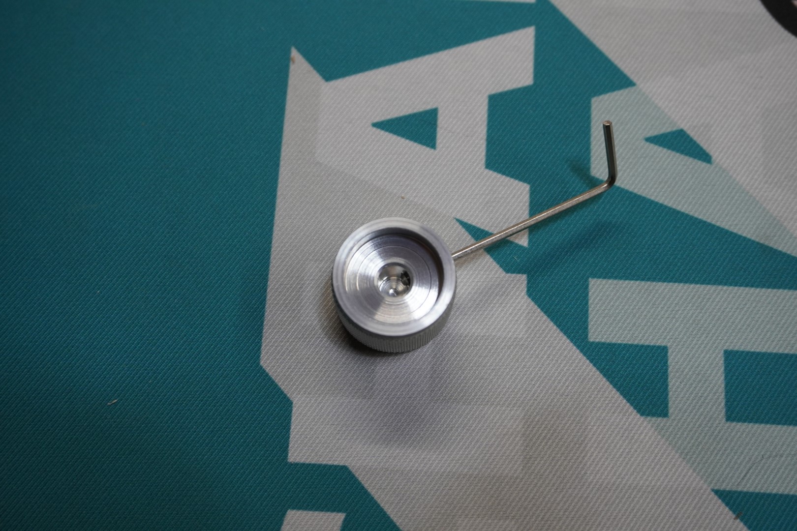
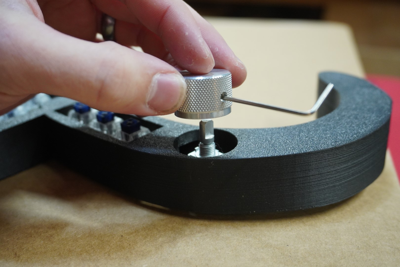
Use the Allen wrench included to bring the set screw inside the knob so that it barely pokes through the internal hole. Place the knob on the encoder shaft so that the set screw interfaces with the flat part of the encoder shaft. After it is in place, tighten the set screw. Be careful not to over tighten with the 3D printed knobs or it will strip. Error on the side of too loose since it can be tightened later.
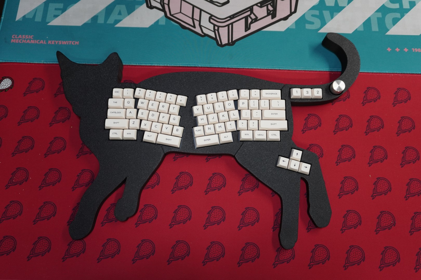
# Install The Keycaps
Install the keycaps. Below is the default key layout.
# Test
Plug in the keyboard, open Vial and navigate to the matrix tester one last time. Press every key and make sure they all work.
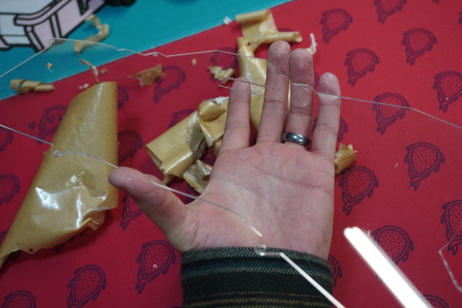
# Install The Clear Backplate
After you've verified that everything works, install the clear back acrylic backplate. Remove the protective paper from the clear acrylic backplate. Flip the FinnGus so the backside is facing you and use the M3x8mm button socket heads to screw it in. Use a box again so that all the weight is not on the encoder/knob. Be careful not to over tighten the acrylic or it might crack.
# Enjoy
That's it! You've Done it! Congratulations! Now it's time to use Vial to program the keyboard to how you like. If you need help using Vial, head on over to the Vial documentation (opens new window)
# Mil-Maxing Tips
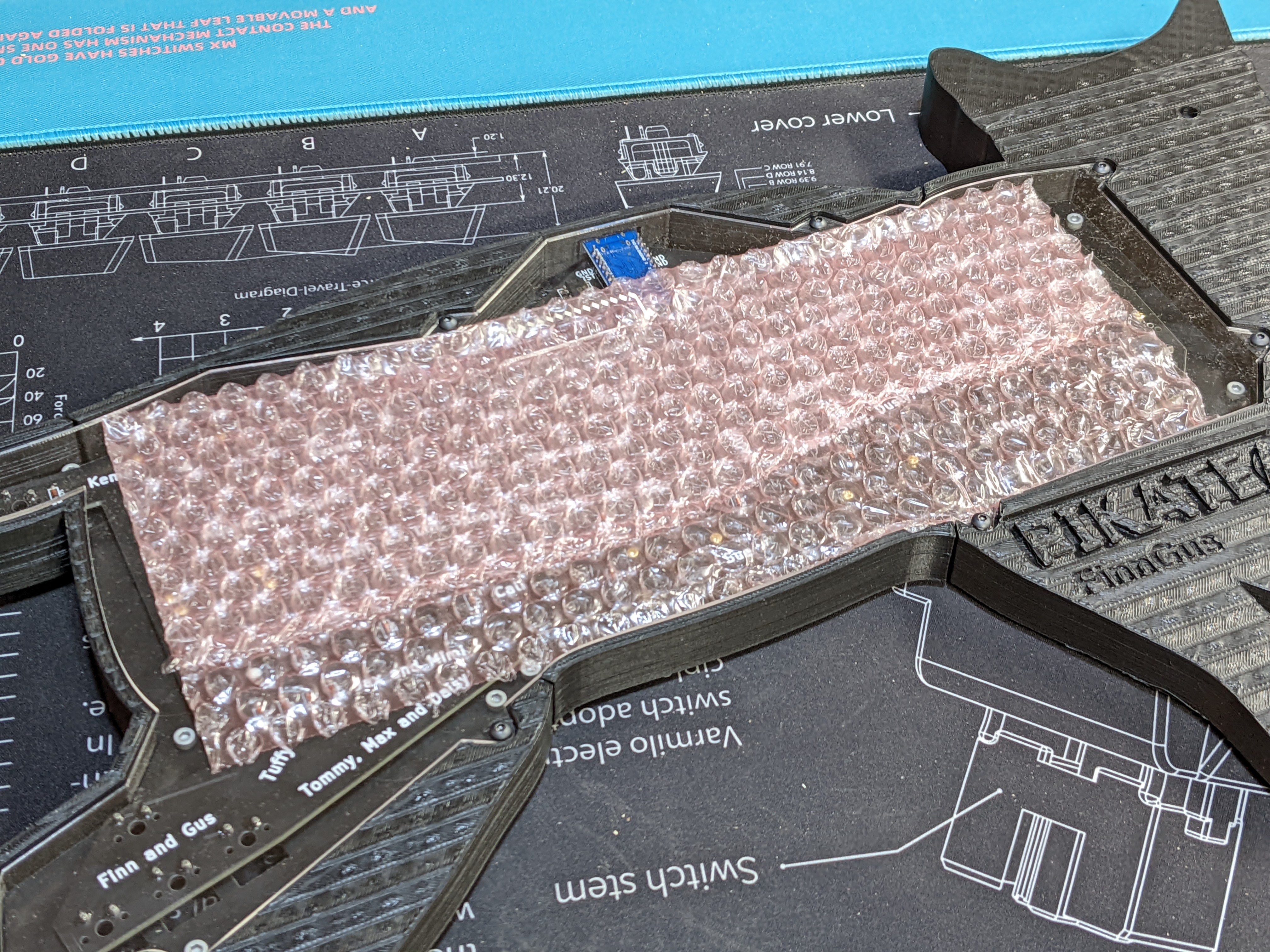
Making this board hotswappable with Mil-Max sockets is possible but the PCB is not specifically designed with this in mind. Other than the area around the encoder the PCB is supported by only the switches and not the case. When install/replacing switches I would first recommend removing the clear backplate, adding foam (the pink bubble wrap we use for packaing works well) and then re installing the backplate. Then install the switches. Finally remove the backplate again, remove the foam and then reinstall the backplate. I know this is tediuous but it's a reliable way to get good results.
# Troubleshooting
Nothing yet. If you have issues, reach out to us and this will be updated accordingly.