# Funky60 Keyboard Kit Assembly Guide
Congrats on receiving your Funky60 Keyboard Kit. This guide will walk you through the process of assembling your device! Please reach out to me at support@pikatea.com or through discord if you have any questions while building your keyboard.
# What's in the Box
You may have more or less things depending on your order but below is the general list.
- Case
- Weight (already attached to case)
- Screws/Hardware
- FR4 Brackets
- Plate(s)
- PCB(s) (AKA the matrix board)
- JST connectors
- JST Cables
- Mainboard
- Mainboard shims of various thicknesses
- Diodes
- Rubber Feet
- O-rings
- reset switch
Here are some things you may have depending on your order
- Kailh hotswap sockets
- More PCBS
- More Plates
- 3D printed case
Other parts needed to complete the keyboard build
- Switches
- Stabilizers
- Funk
Please double check everything is here! There is a small chance we forgot something or that your order is wrong; in the case this is true, please reach out via email at support@pikatea.com and we will work with you to make it right.
# Gather Required Materials
You will need everything that comes with the kit as well as a few other items. Those additional items include:
- USB-C cable
- Soldering iron and solder
- Allen wrenches (1.5mm and 2.5mm)
- Flush cut snips
- About 3-4 hours time
Now that you have everything you need, lets get started!
# Prepare The PCB
The PCB is the most complicated part so we've broken it down into several steps. Please pay special attention to the details on these steps. I'd recommend reading through this entire section before getting started. It's important to be as careful as possible to not scratch the PCB and damage it. Take your time!
- Flash the Firmware
- Mainboard
- Sockets (If Hotswapping)
- Solder in the Diodes
- Add JST Connectors
- Stabilizers
- Verify and Test
# 1. Flash the Firmware
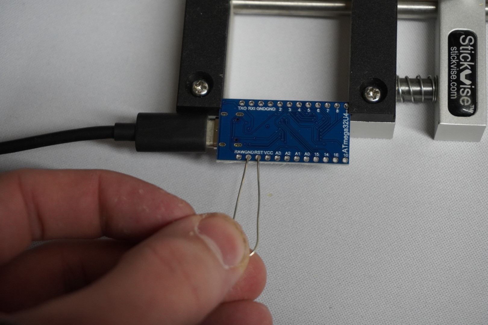
Let's start with flashing the firmware onto the included Pro Micro to make sure that is working. Plug it into your computer using a USB-C cable.
We already have a generic guide for flashing firmware which is here. Follow that guide and use the Funky60 firmware that matches they layout you plan to use which can be downloaded from that page. Since there is no reset button on the Pro Micro, reset the device by connecting the pins RESET and GND with a metal object (a bent paper clip works well). Download and install Vial (opens new window) and make sure your computer recognizes the device as a Funky60 before moving on.
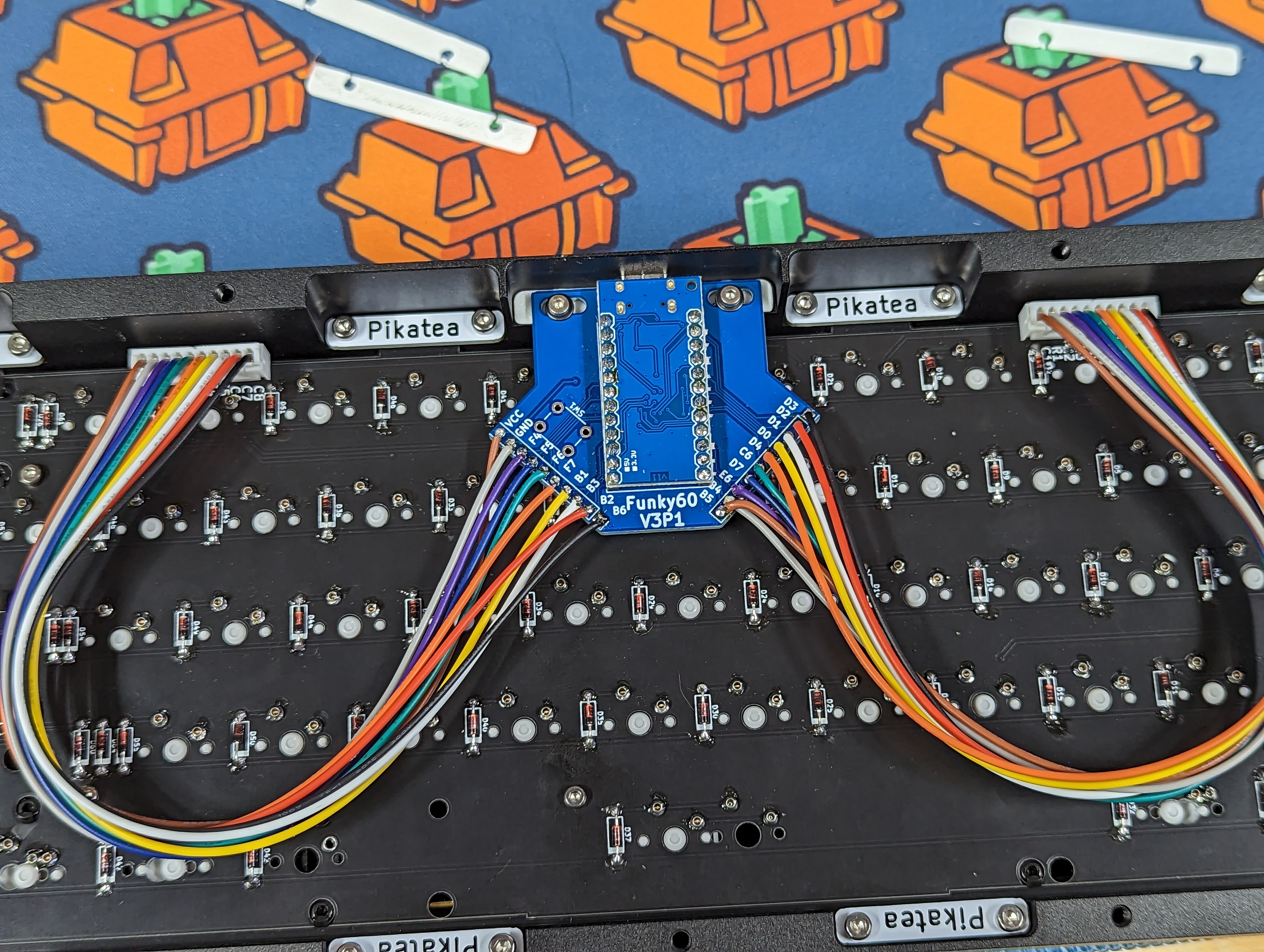
# 2. Mainboard
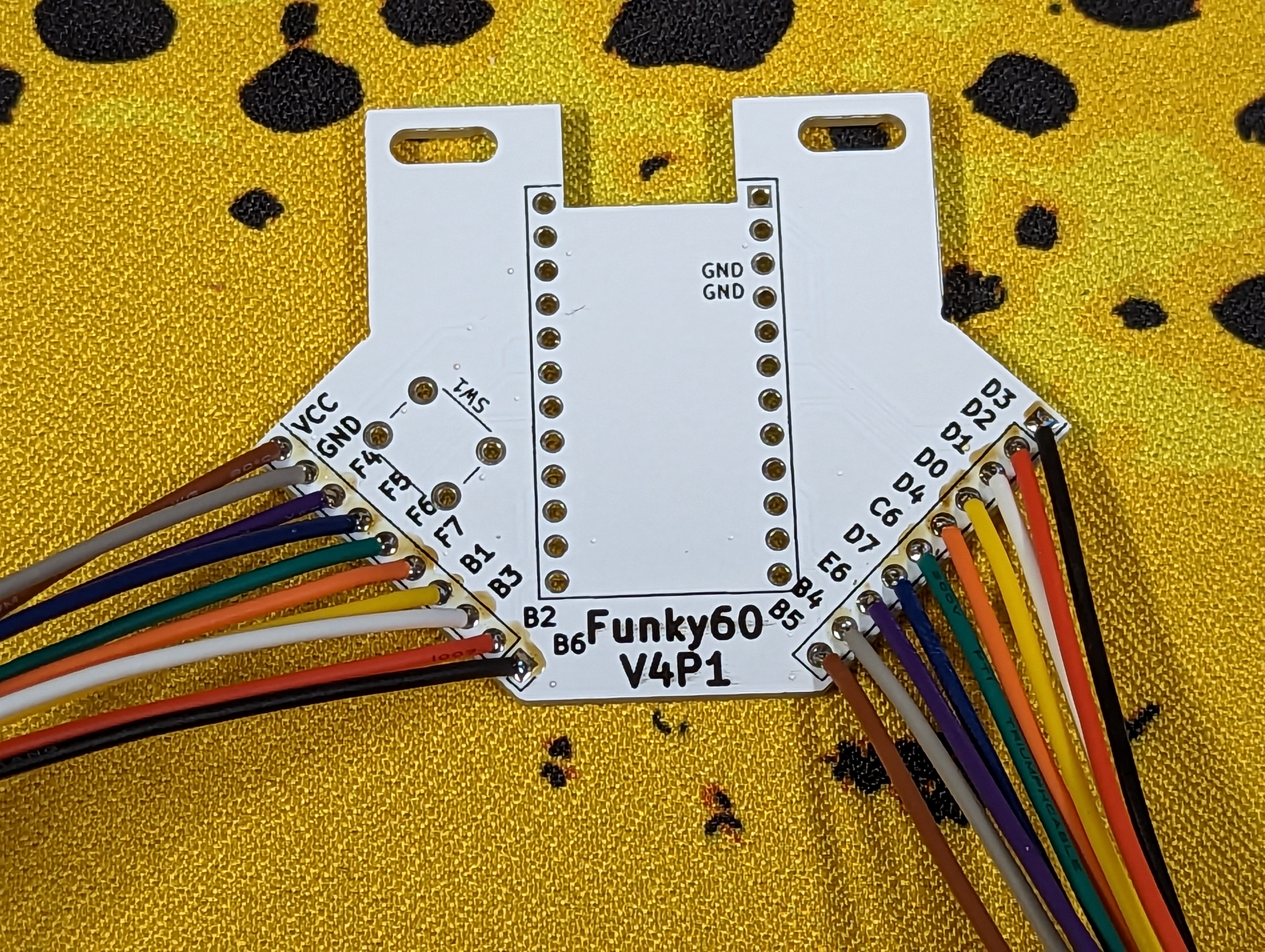
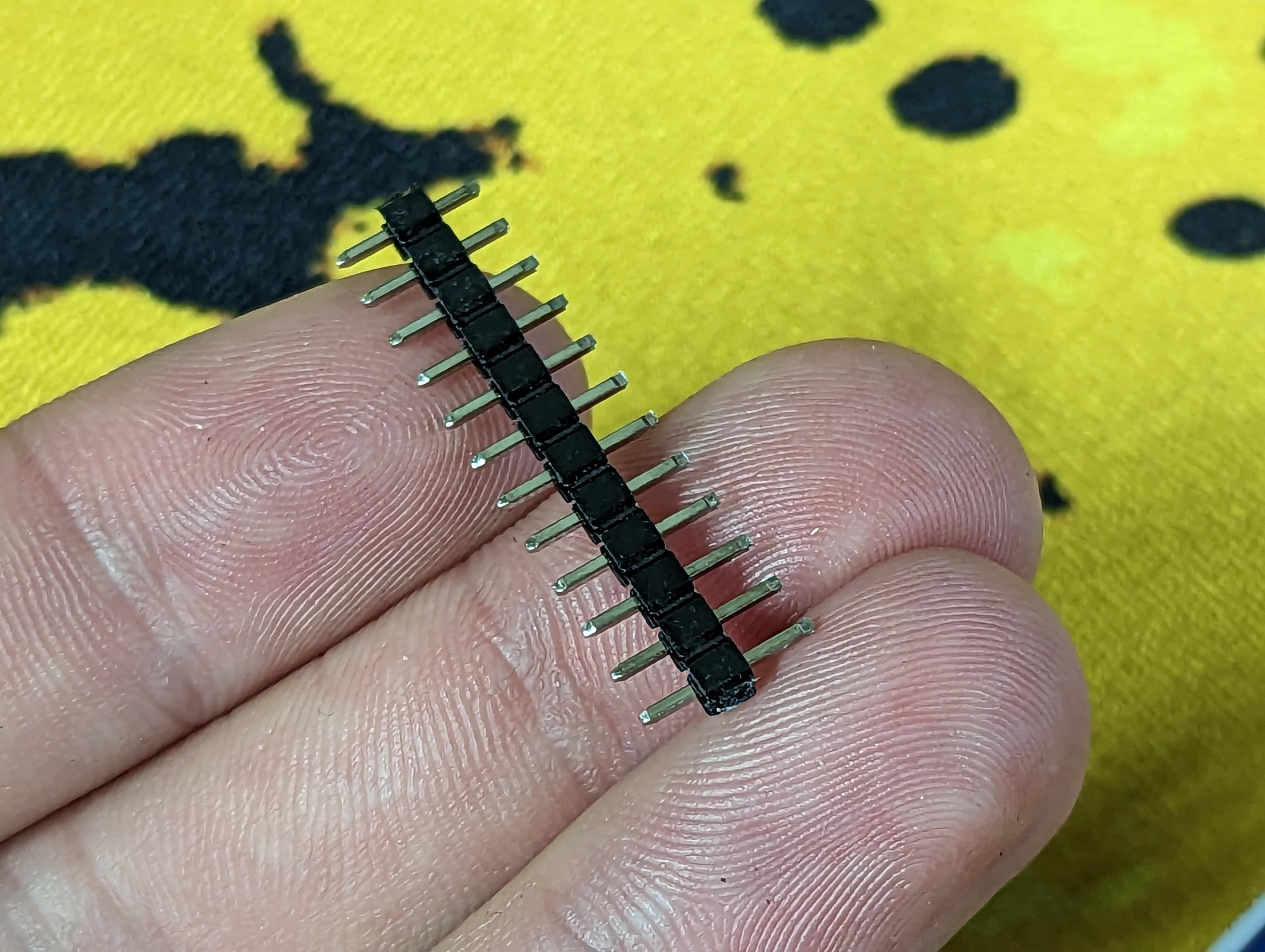
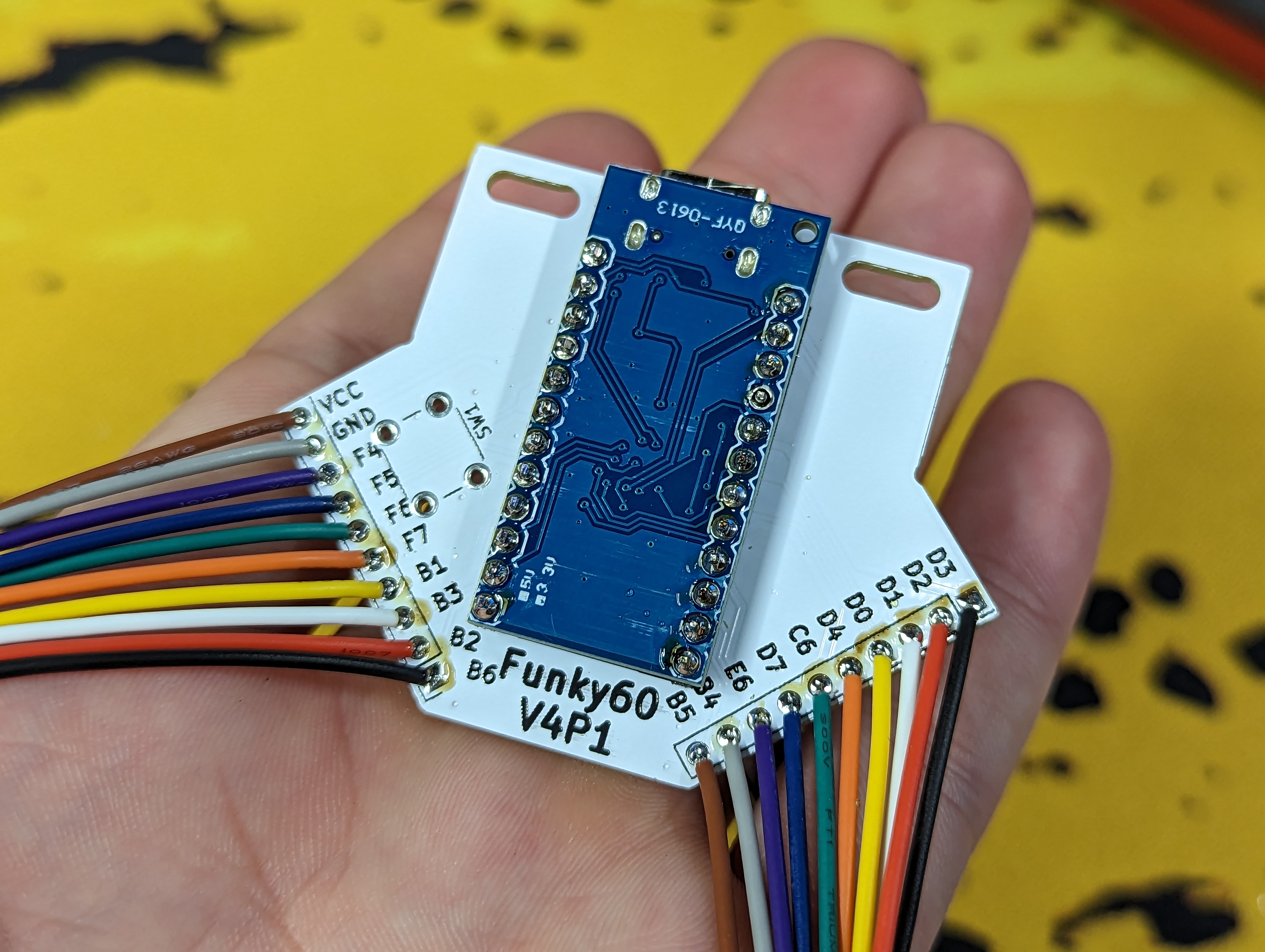
Solder the JST cables to the daughterboard. Please pay special attention to the color of the wires. It is important they are correct. No wires should "cross-over" any other wires. Snip the headers so they do not protrude much from the MCU. If you do not do this, the backplate will not fit. Solder the reset button if you want.
# 3. Sockets (If Hotswapping)
If you have the Kailh hotswap PCB, now is the time to Solder in the sockets.
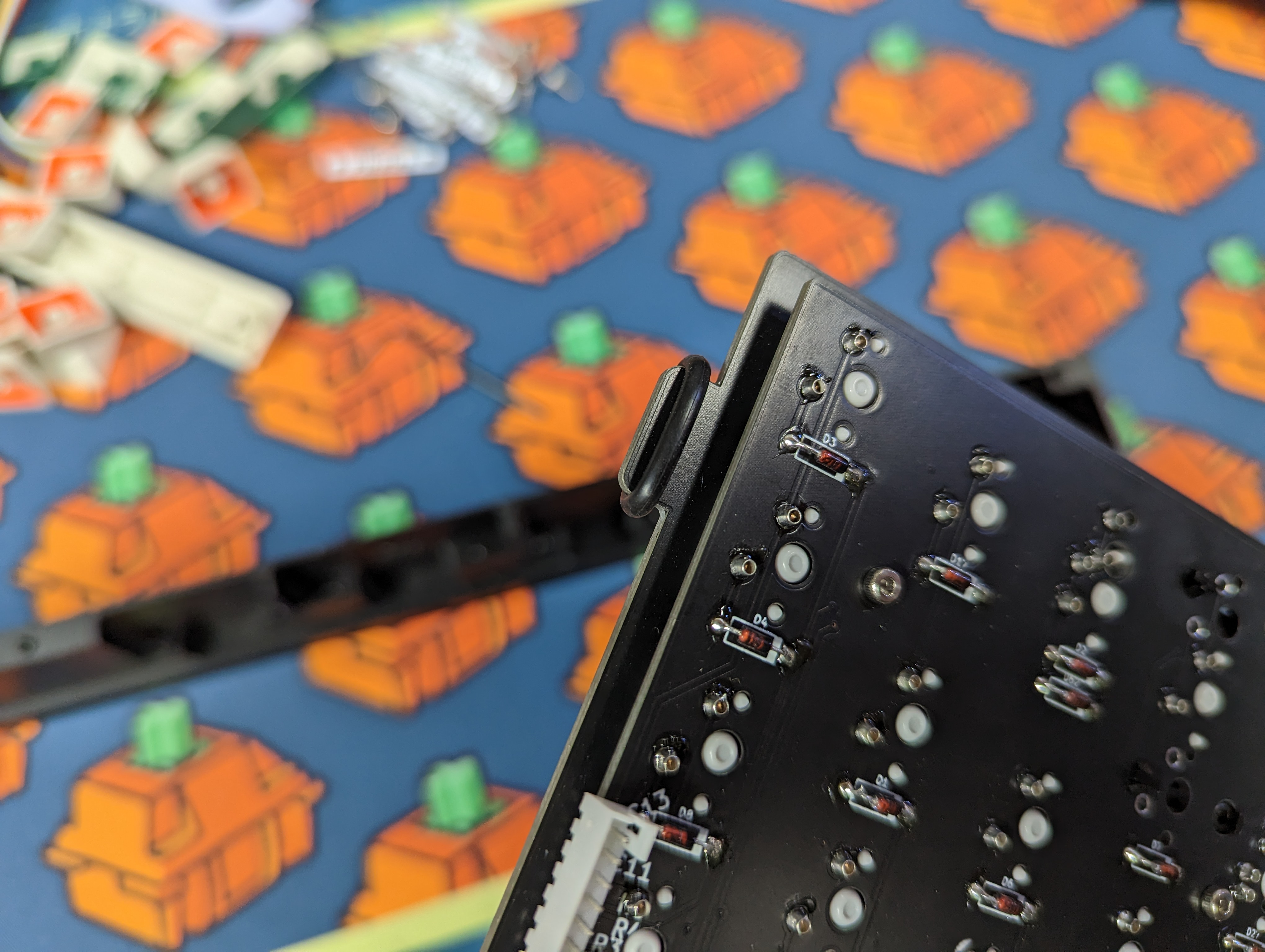
# 4. Solder in the Diodes
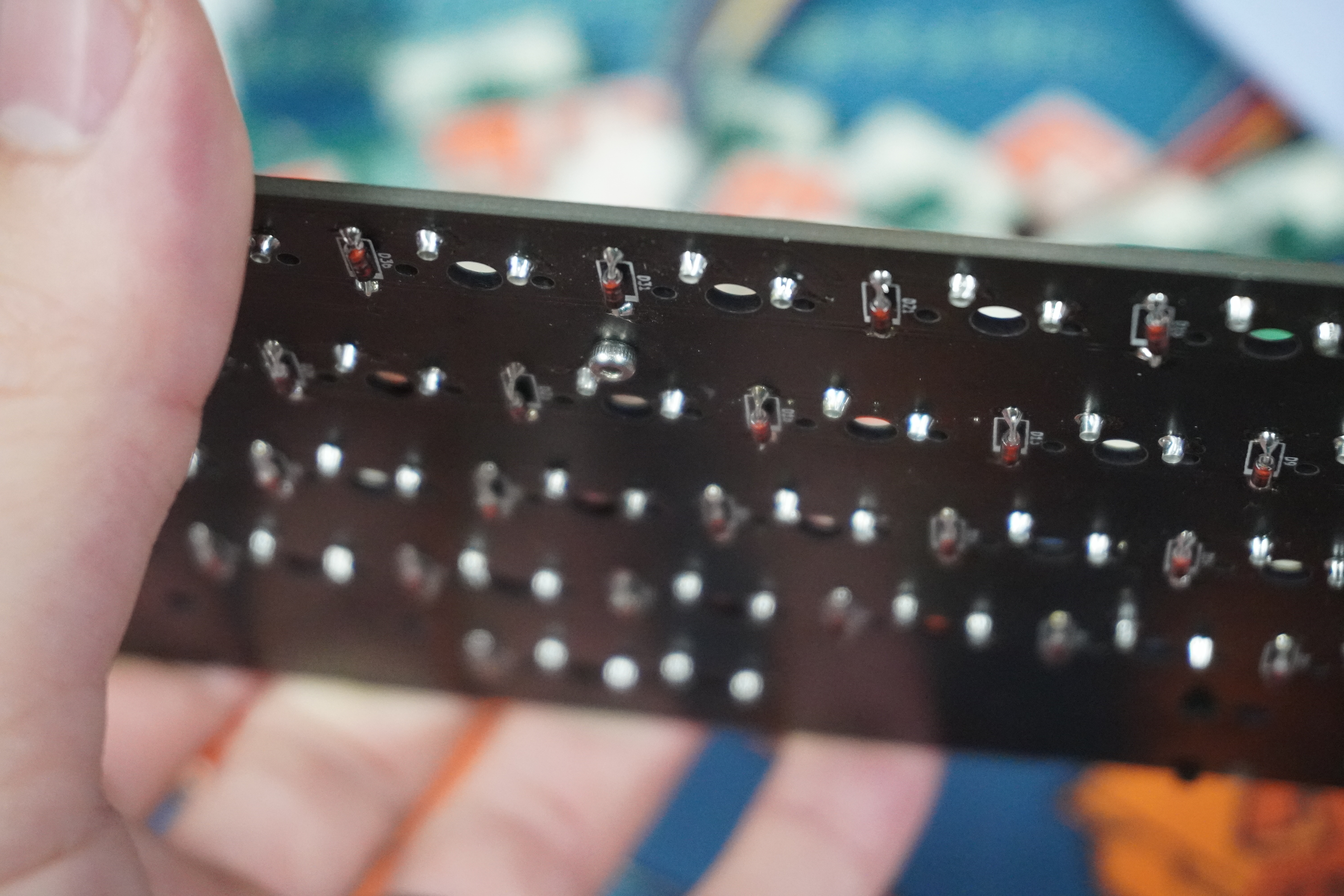
- Bend the diode and insert it into the PCB being careful it is the correct orientation. The black bar on the diode matches with the thicker white bar on the PCB.
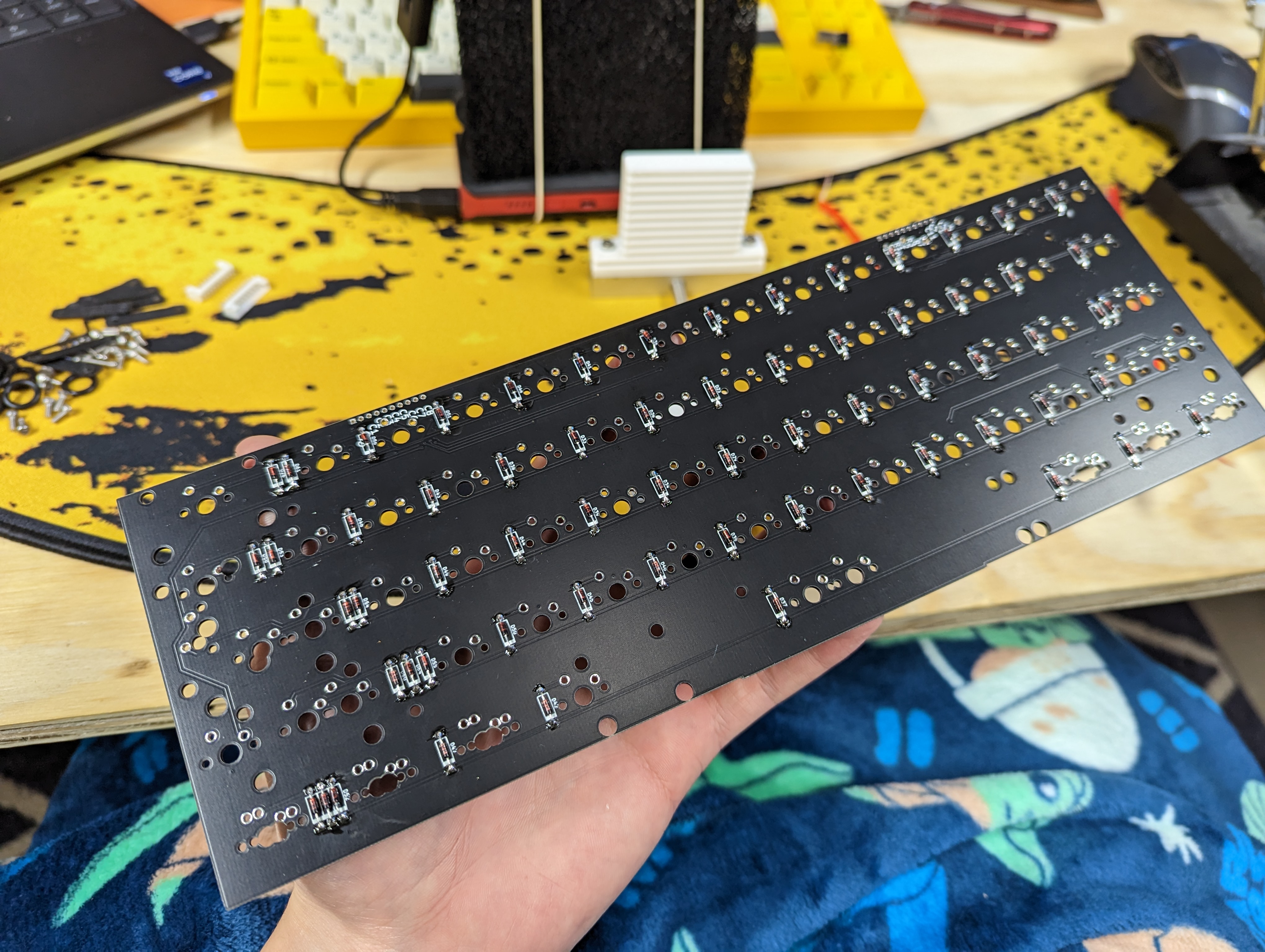
- After the diode is inserted, bend the leads outwards so it stays in place. Repeat steps 1 and 2 for each diode.
- Finally after each diode has been inserted, solder each one.
- Bend the diodes legs straight and use flush cuts to them off. Be careful not to scratch the PCB when doing this.
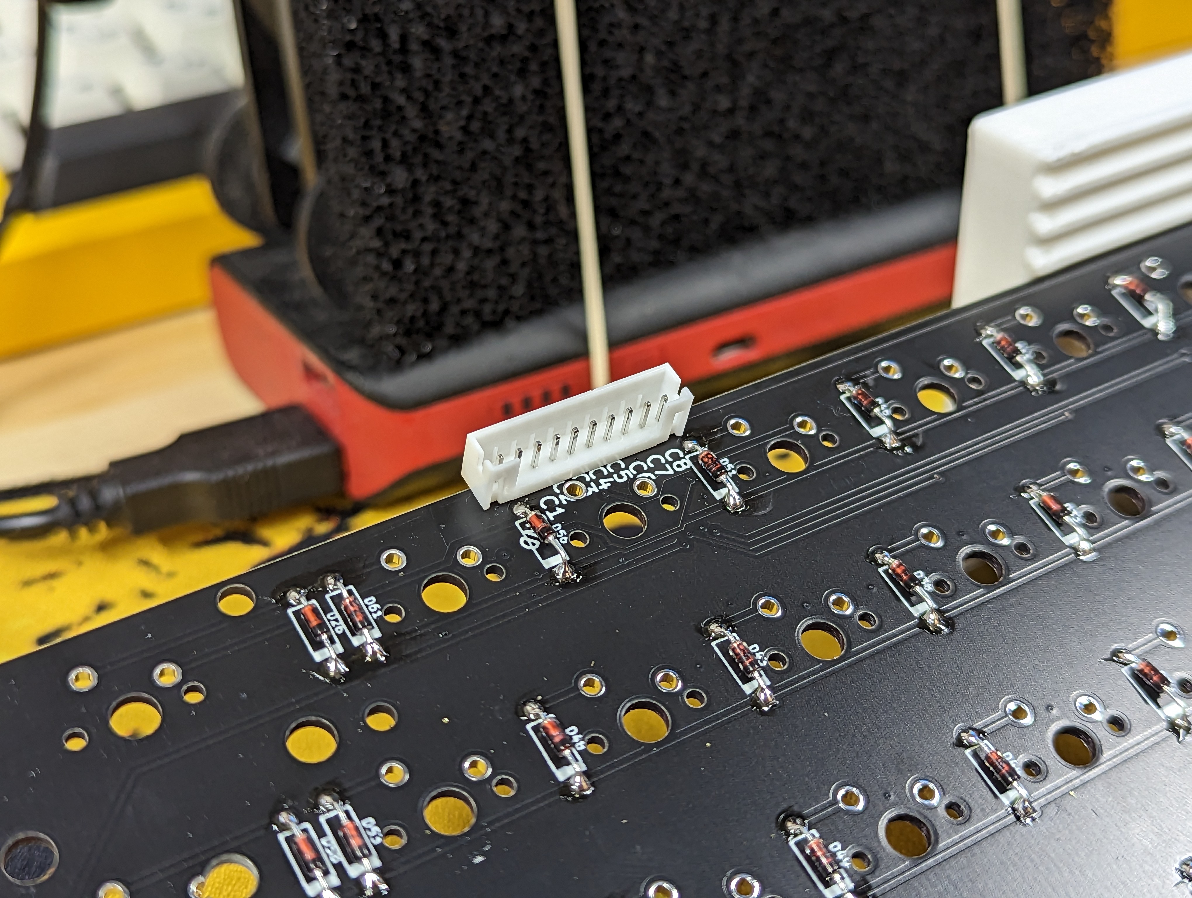
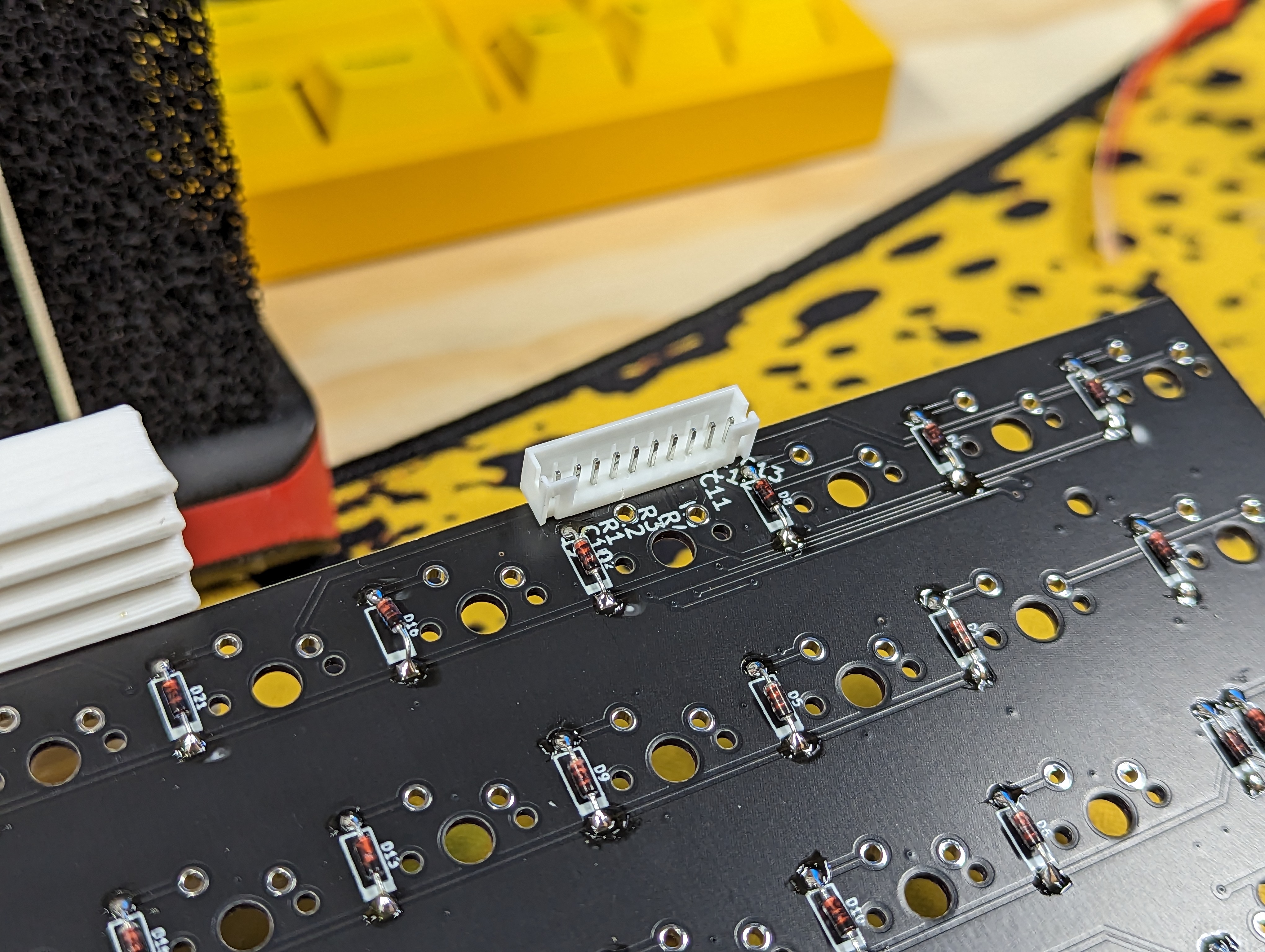
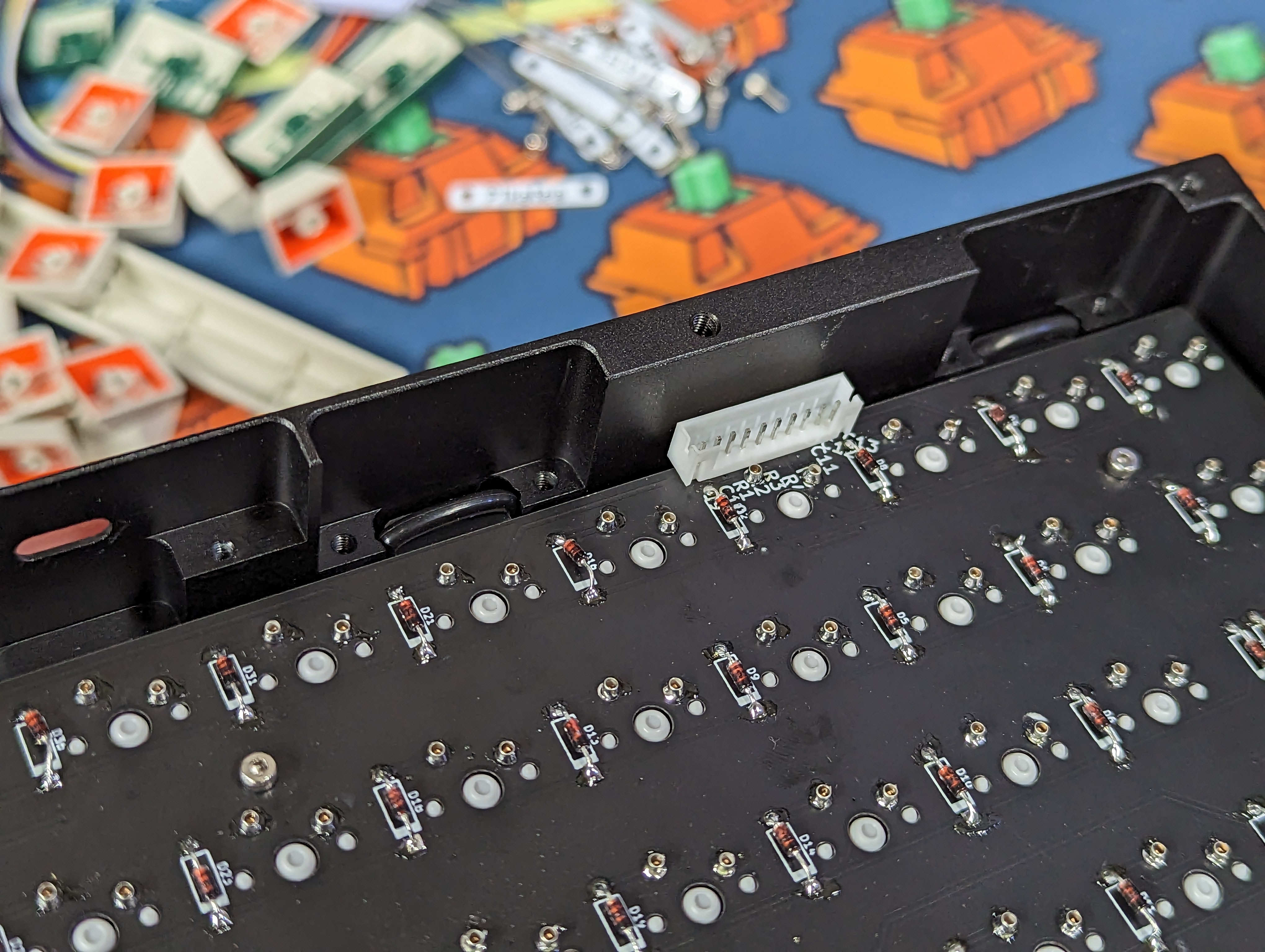
# 5. Add JST Connectors
Find the JST connector for your PCB. It should be near the backside of the keyboard. Both Normal and Funky layouts look like this.
# 6. Stabilizers
Install the PCB mounted stabilizers. They either screw in or clip in. Below are a few links that explain keyboard stabilizers and how to install them.
# 7. Verify and Test
While not strickly necessary, I like to test the PCB at this point before I solder in the switches. It's much easier to fix issues now if they come up.
Plug in the PCB. Open Vial and select the keyboard in the top drop down menu. From there, select the Matrix Tester tab. This will show you every keypress. Test each key by using a metal object and connecting the switch pads together.
# Switches and Plate
Depending on if you are hotswapping or soldering switches, you'll want to follow slightly different steps
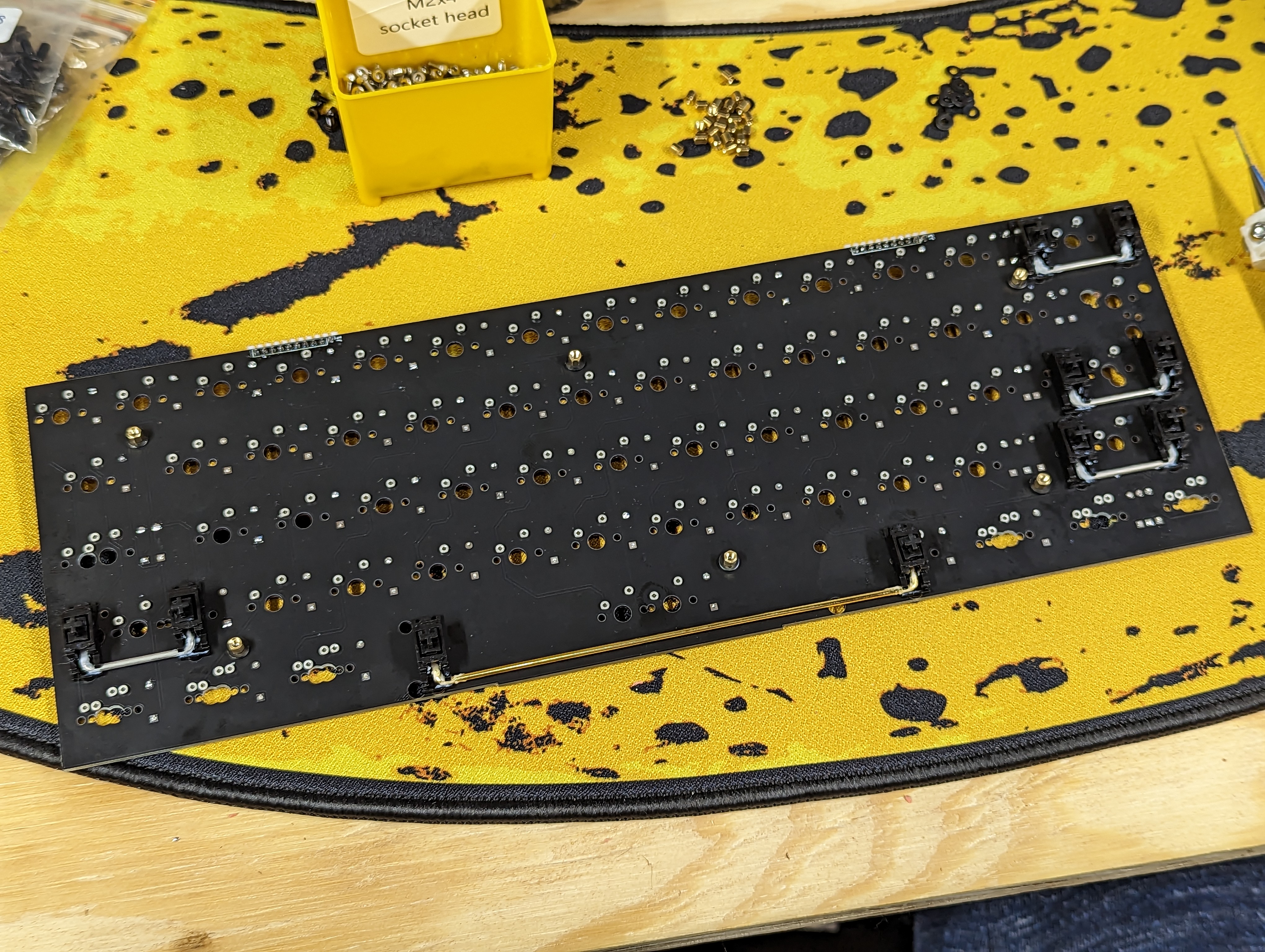
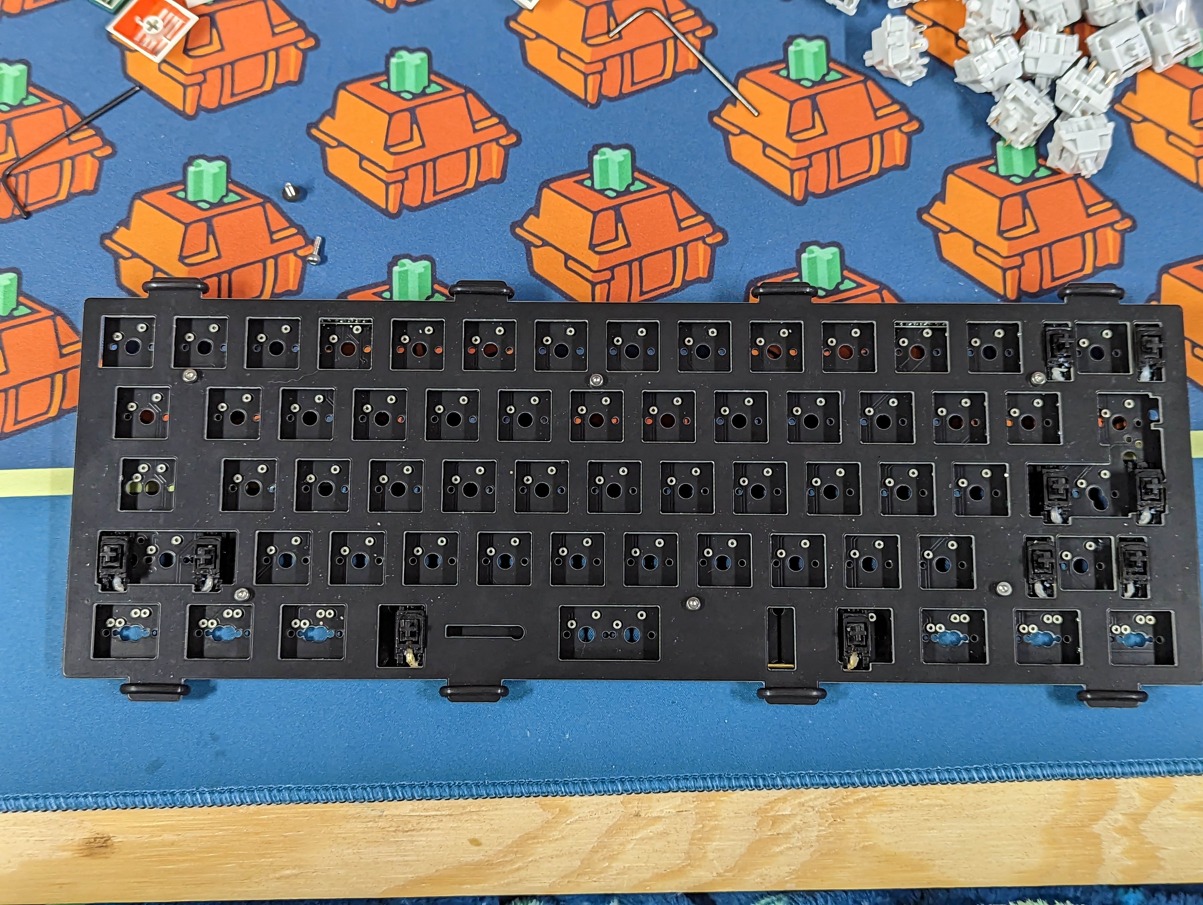
# Hotswapping (Kailh or Mil-Max)
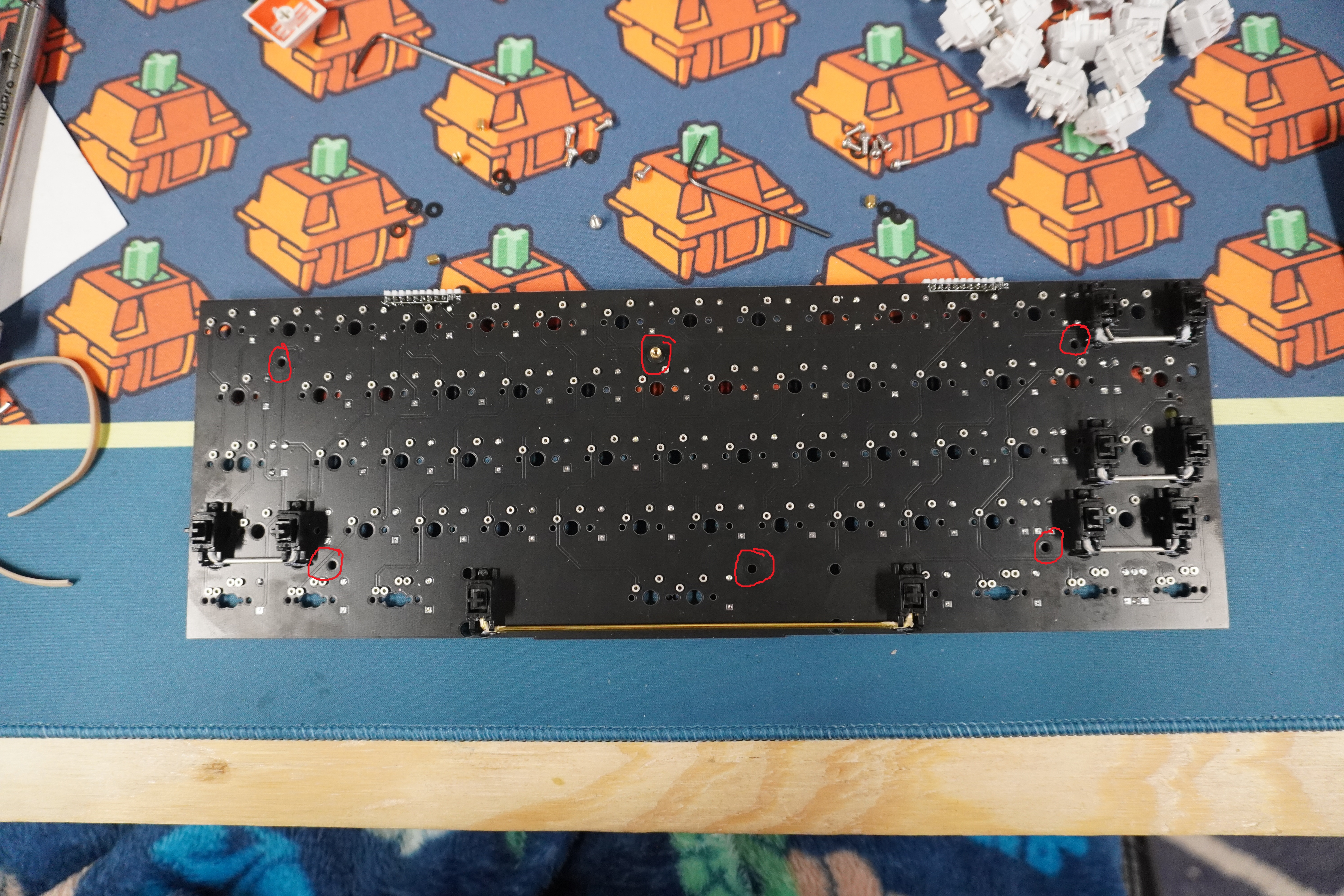
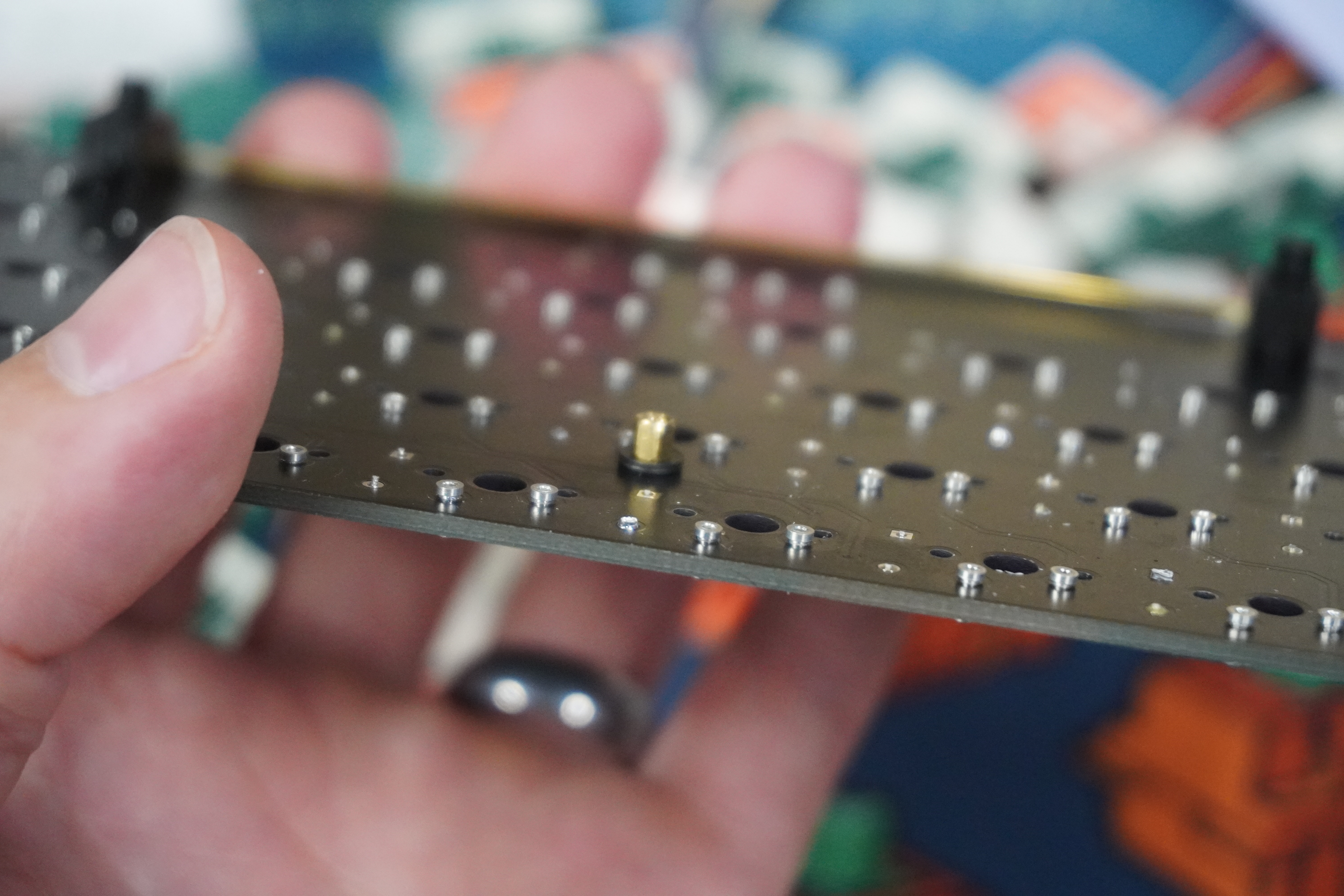
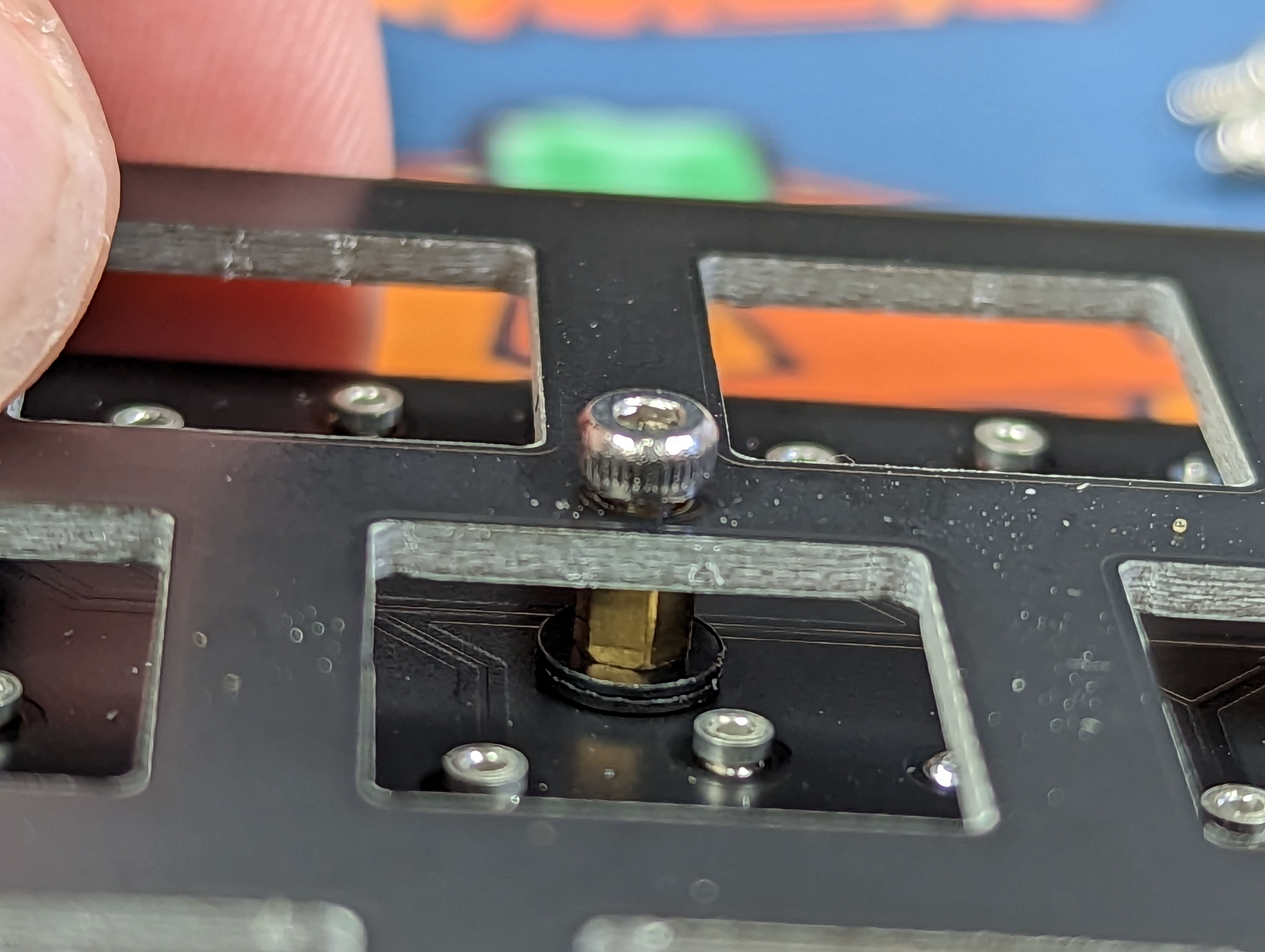
Use the included hardware labeled "Hot-Swap Socket Hardware" to attach the PCB and plate together. Use M2x4mm bolts combined with 2 washers and 1 m2x3mm standoff as shown in all 6 locations. (These locations are going to change with the final GB for various reasons)
Add the plate on top. Add the other m2x4mm bolts. The plate will be loose which is by design. Do not overtighten!.
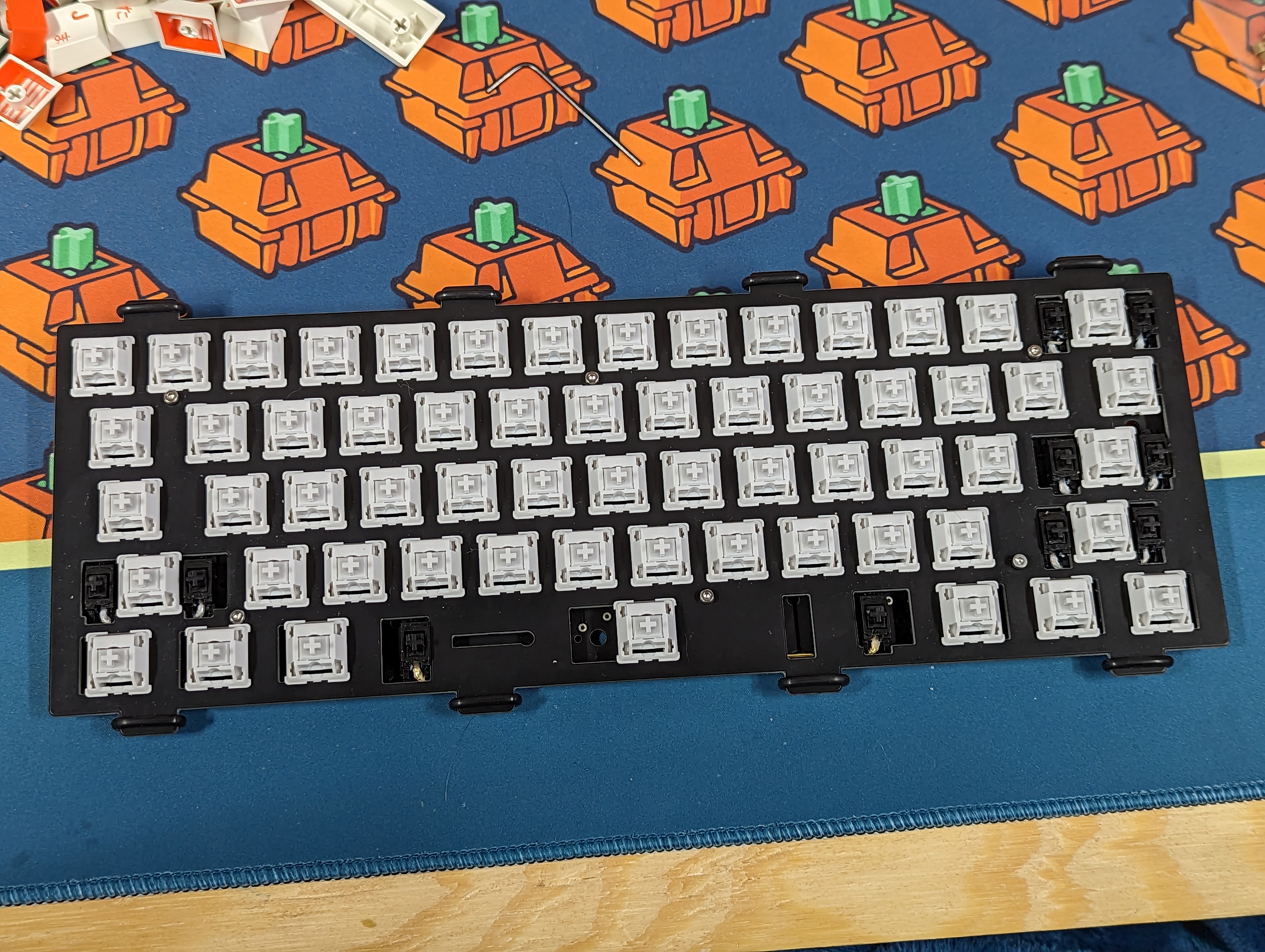
After the PCB and Plate are together, Insert the switches of your choice!
# Soldering
Insert a few switches into the plate. Combine the Plate and PCB together. Solder 1/2 of the switch pins for a few switches so the assembly stays together. Insert the remaining switches. Solder the 1/2 of the pins of the rest of the switches. After verifying all the switches are flush and well seated, solder the remaining pin on each switches
(SOLDERING SWITCH SECTION STILL WIP)
After installing the switches in whichever way you choose, add the o-rings to the plate tabs. Make sure they fit in the small groves of the tabs
# Final Assembly
Unscrew the brass backplate with a 2mm Allen or T-handle.
Insert the PCB+plate assembly into the aluminum case.
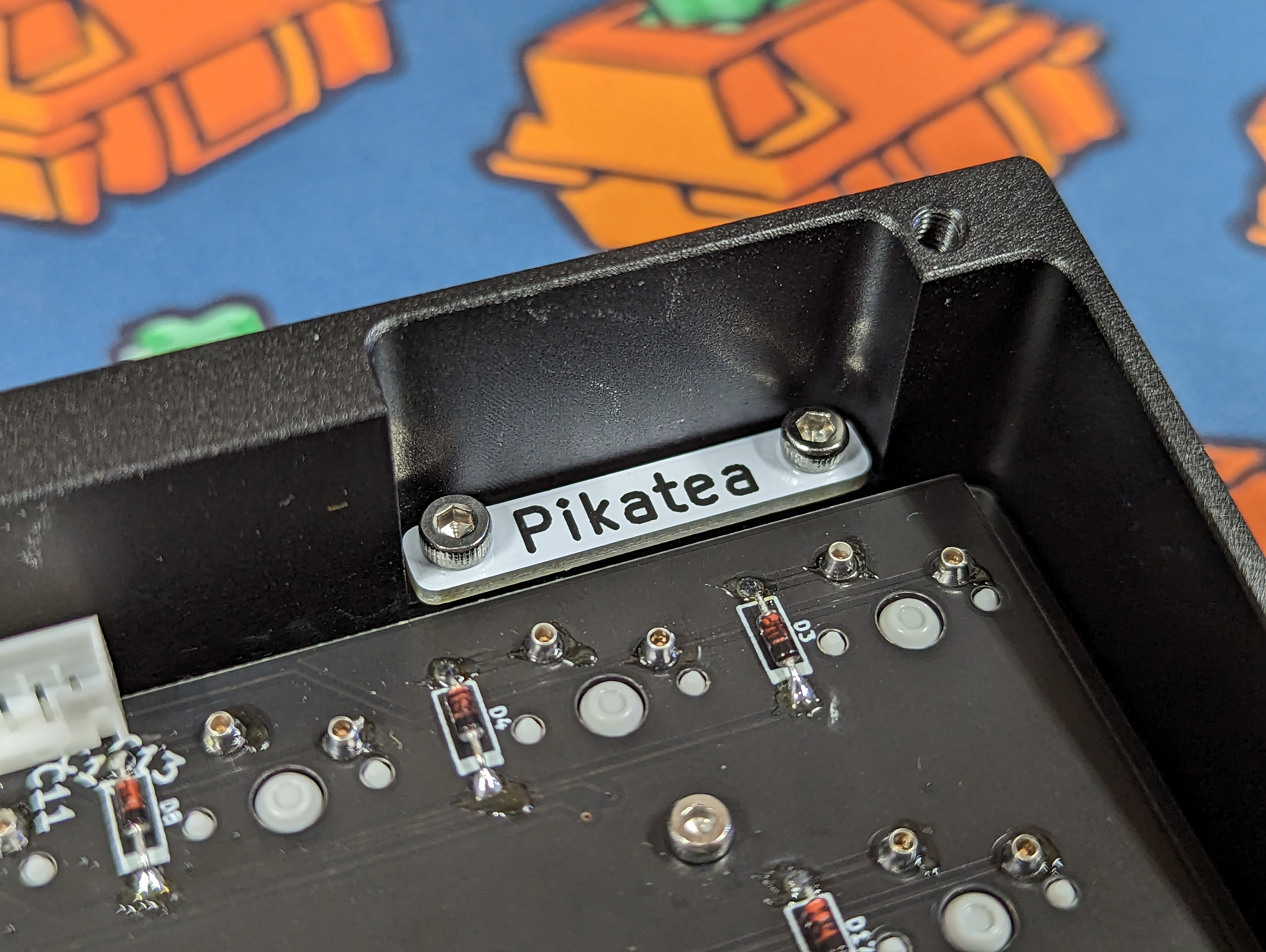
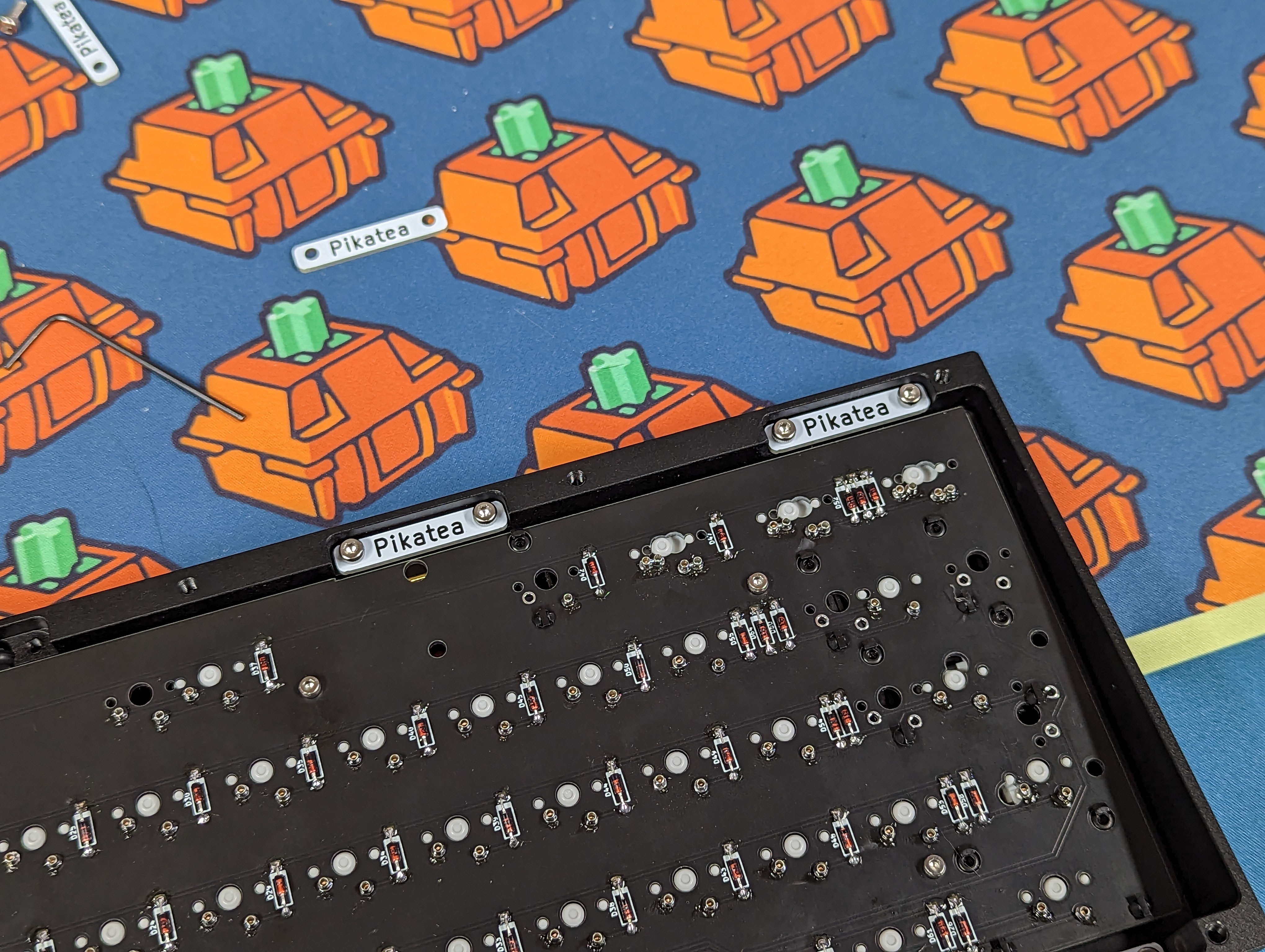
Add the brackets with M3x6mm bolts with a 2mm Allen or T-handle
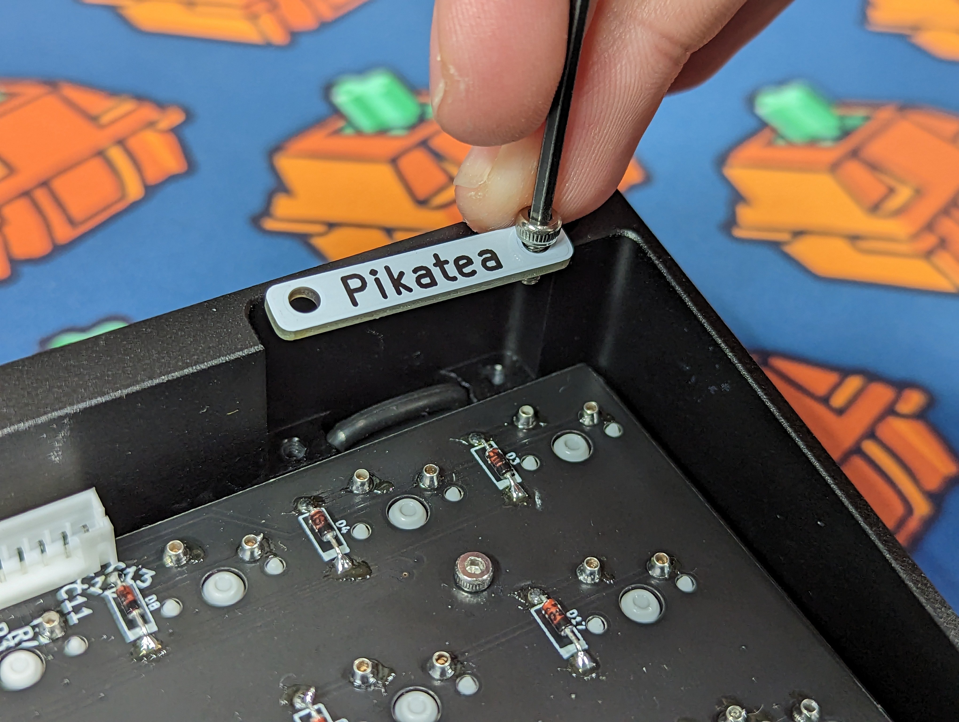
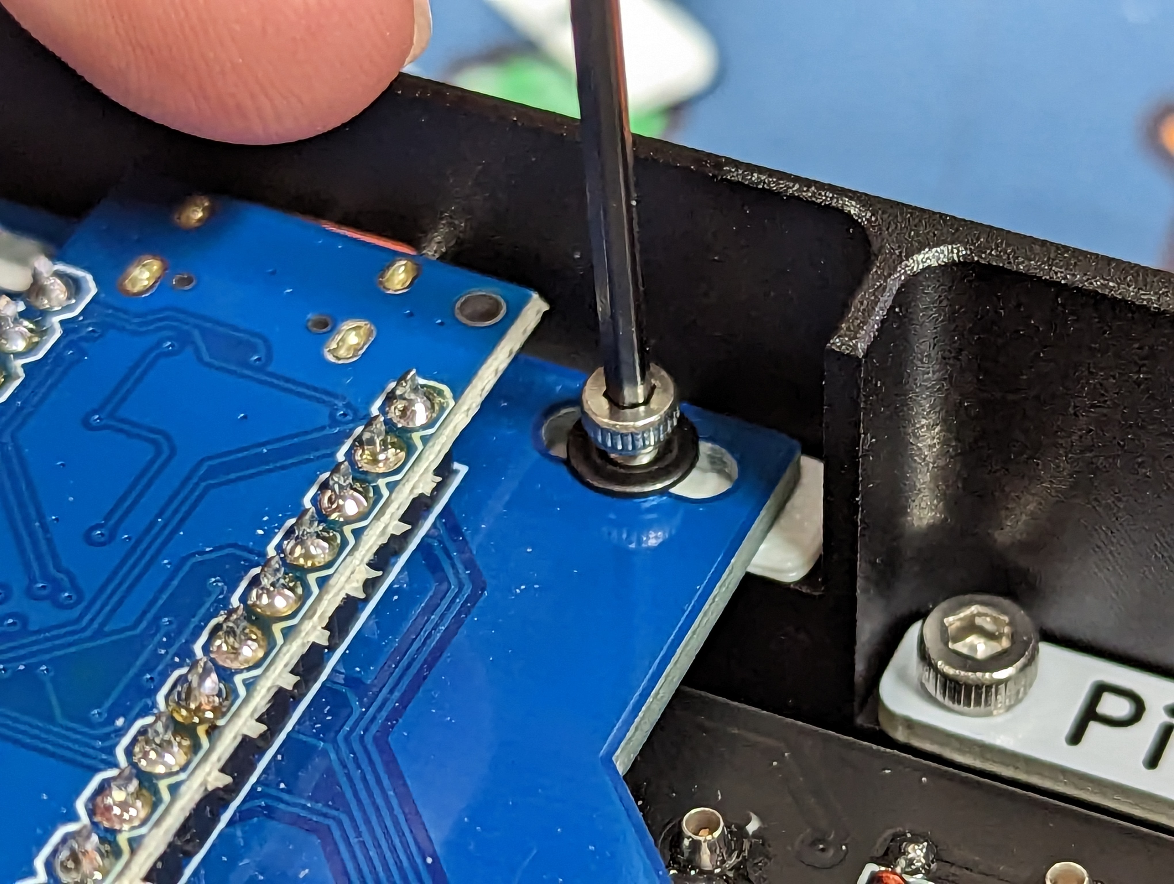
Pick a shim for the daughterboard. I typically use the middle one but depending on how well (or badly) you soldered, you may have to pick a different one. Place the shim on the case near the USB port hole
![]()
Screw in the Daughterboard with m2.5x8mm bolts and a washer. Be carefull not to pinch the USB port if you did not pick the right shim. I personally like to have the USB port NOT poking outside the case.
Connect the JST connectors
Test the board with Vial.
Add the backplate weight and rubber feets.
That's it!
# Troubleshooting
Nothing here yet. If you have issues, reach out to us and this will be updated accordingly.