# Pikatea Macropad R26 Desktop Kit Assembly Guide (round 1)
Congratulations on receiving your Pikatea Macropad R26 Desktop Kit. This guide will walk you through the assembly process. Please email support or ask on Discord if you have any questions. This is for the round 1 macropad which does not include LED support.
Here is a video for those that prefer it.
# What's in the Box
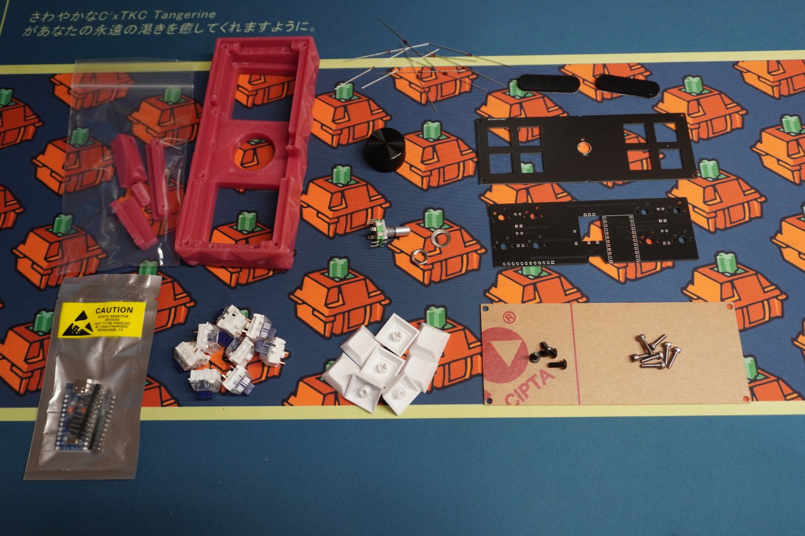
# All Orders
- (1) FR4 Top plate
- (1) Circuit board
- (1) Rotary encoder with hardware (washer and nut)
- (1) 1/16th inch Allen wrench
- (1) Hardware
- (10) Diodes
# Some Orders/Optional Items
- (1) Acrylic Backplate
- (1) Arduino Pro Micro with headers
- (8) Mechanical keyboard switches
- (8) Keycaps
- (1) Knob
# 3D printed
- (1) Shard or Flat style case
- (1) Set of brackets
# 3D Print Parts If Necessary
You may have opted to 3D print the case yourself. Here are files under R26. You'll need to print a case (either flat or shard) and a set of brackets.
CAD files are provided so feel free to modify and make your own designs.
# Gather Required Materials
You will need everything that comes with the kit as well as a few other items. Those additional items include:
- Soldering iron and solder
- Flush cut snips
- wire cutters
- Pliers, adjustable wrench or 10mm size socket/wrench for the rotary encoder hardware.
- Roll of tape (any kind will do)
Now that you have everything you need, lets get started!
# Flash the Pro Micro
You will want to flash the Pro Micro before any soldering to make sure that it works. Plug it into your computer using a USB-C cable.
We already have a generic guide for flashing .hex firmware. Follow that guide and use the R26 Desktop firmware which can be downloaded from the Firmware download list. Since there is no reset button on the Pro Micro, reset the device by connecting the pins RESET and GND with a metal object (a bent paper clip works well). Download and install Vial (opens new window) and make sure your computer recognizes the device as a R26 Desktop before moving on.
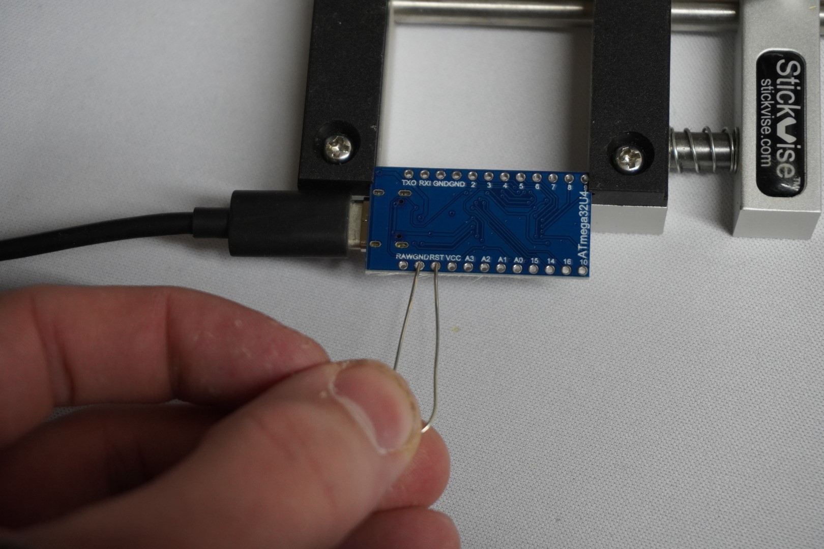
While techincally this step can be done later, it's very highly recommended to test the pro micro before soldering it with the kit. It will save lots of time while assembling. Contact support or ask in our Discord if you are having issues with this step.
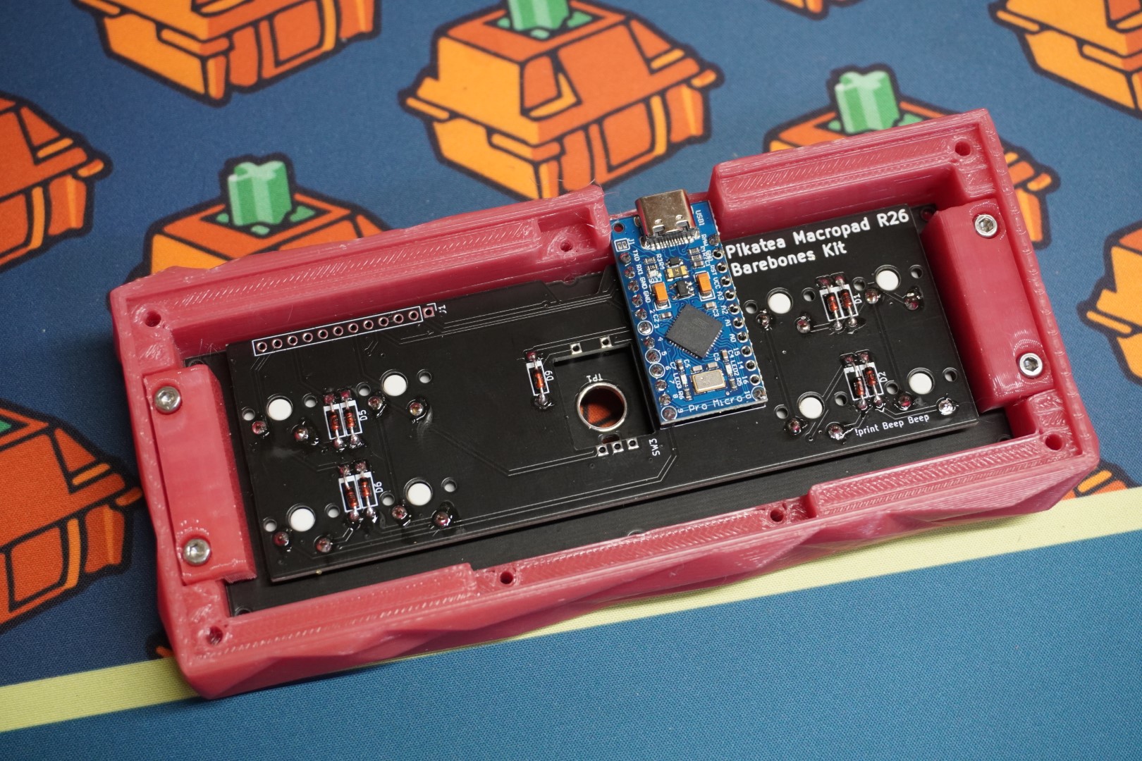
# Prepare the Circuit Board
Let's begin by preparing the PCB or Circuit Board. Please pay attention to the orientation of components.
# Install The Diodes
The first thing to do is solder the 9 diodes. Be careful to install them in the correct orienatation. Bend each diode and insert it into the footprint with the black stip on the diode matching up with the Bold part of the footprint. Insert the diodes and then bend them so they stay in place.


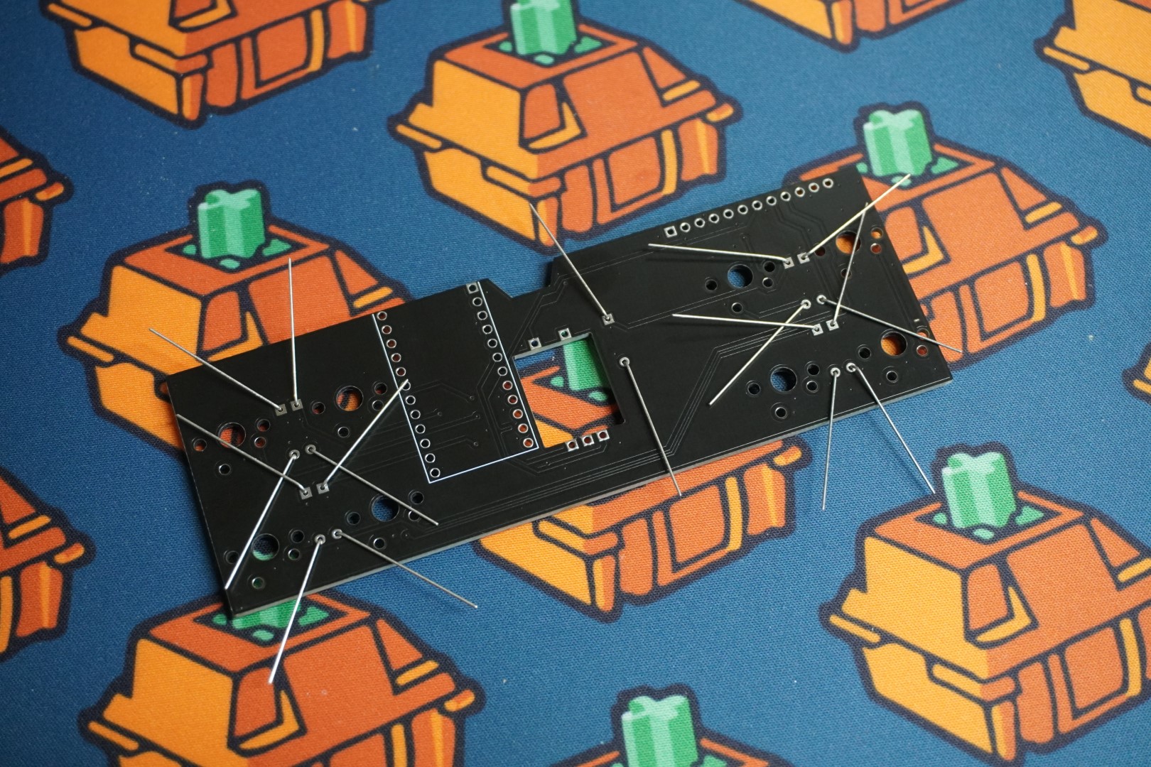
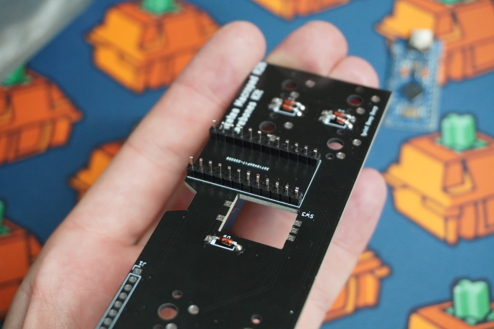
# Solder The Diodes
With each diode in place, Solder them to be permanently secured. Bend the leds on the backside upwards and trim them with flush cuts.


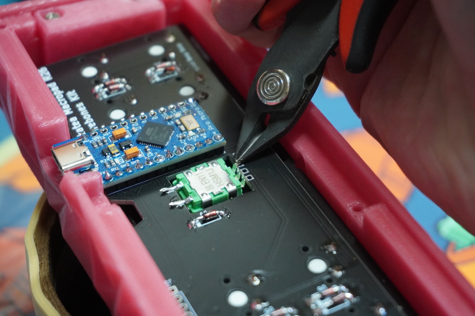
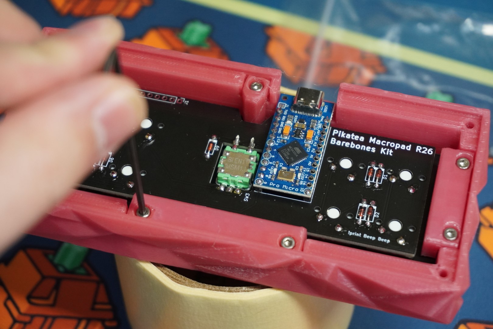
# Trim The Headers
The headers need to be trimmed or the backplate will not fit. Cut the longer side of the headers in half as shown. It doesn't have to be precise.


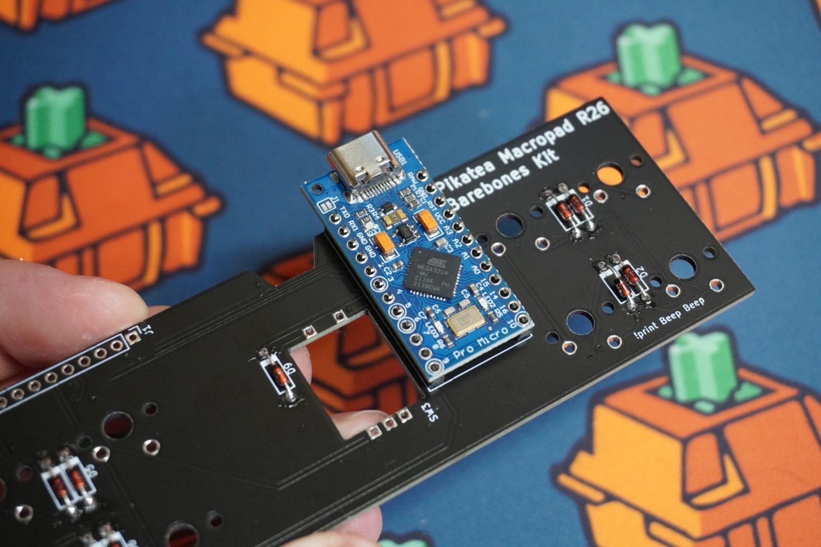
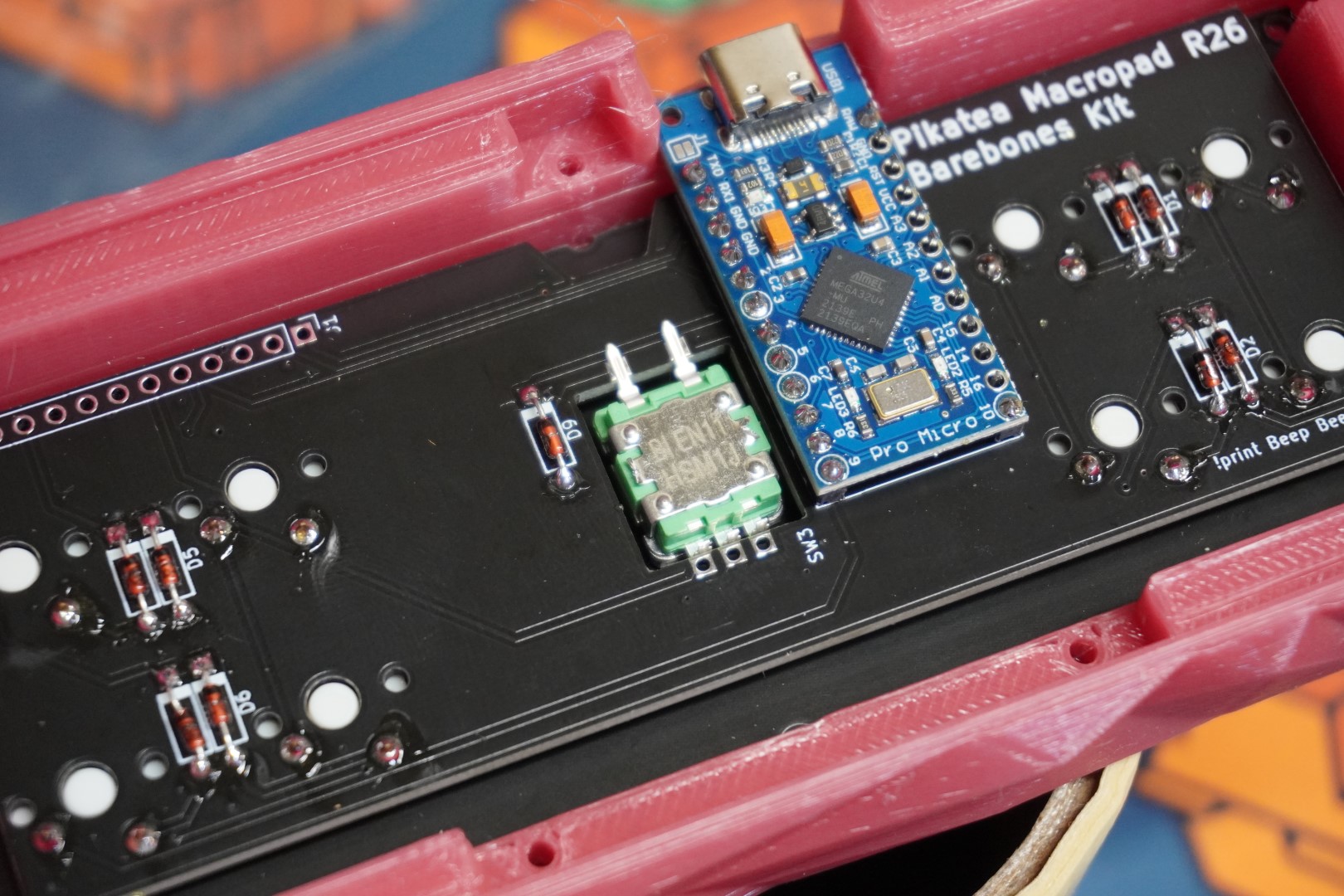
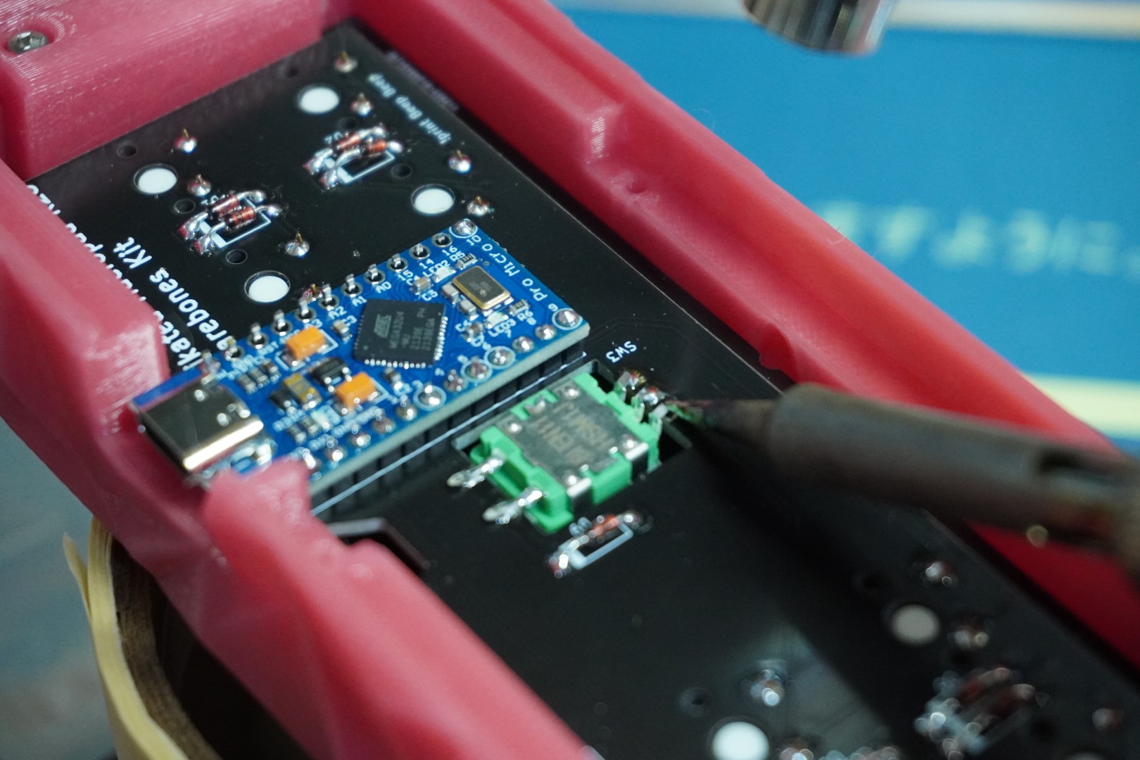
# Solder The Pro Micro
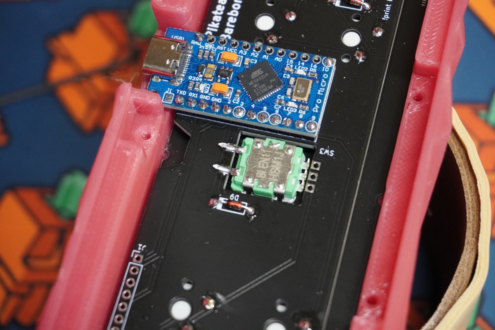
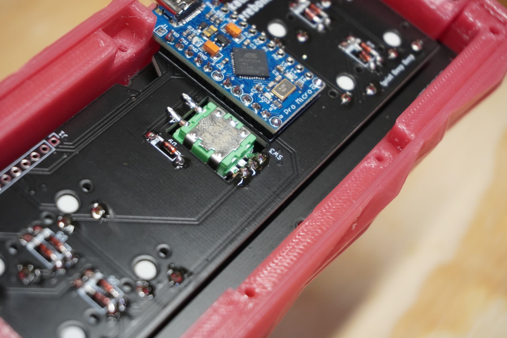
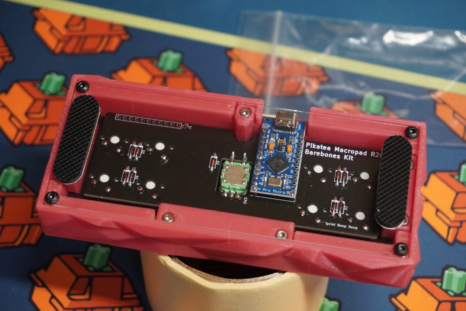
With the Pro Micro confirmed to be working, let's go ahead and install it. Please pay special attention to the orienation of the Pro Micro. Insert the headers with the "cut" side facing you. Place the Pro Micro on top as shown.
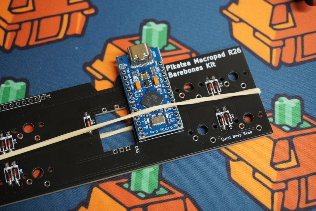
Use a rubber band to hold it in place and solder the 4 corners of each side.
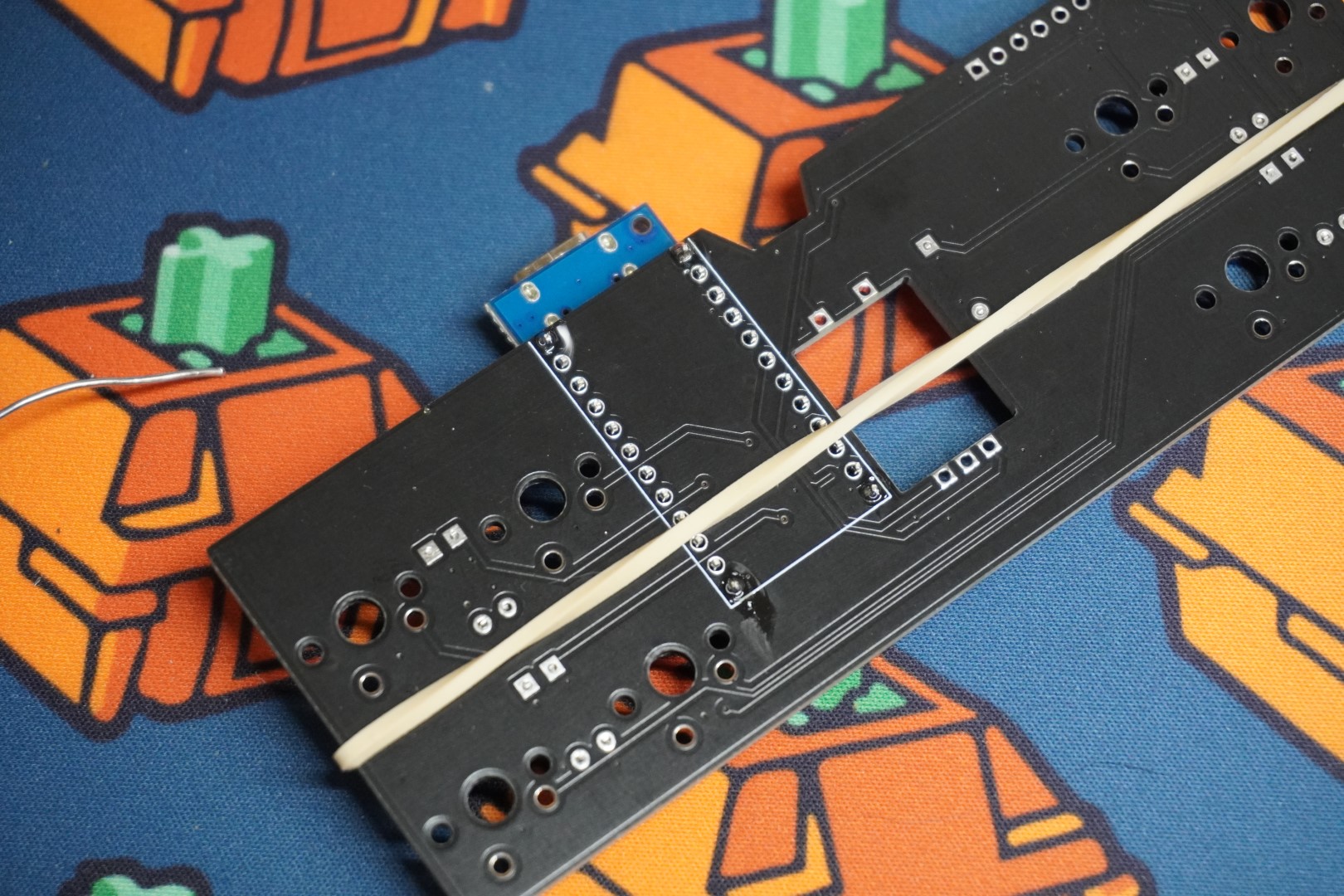
Remove the rubber band and solder both sides of the header closest to the encoder/knob hole. The other header is not necessary. With that, the PCB is done! Verify with the pictures below.
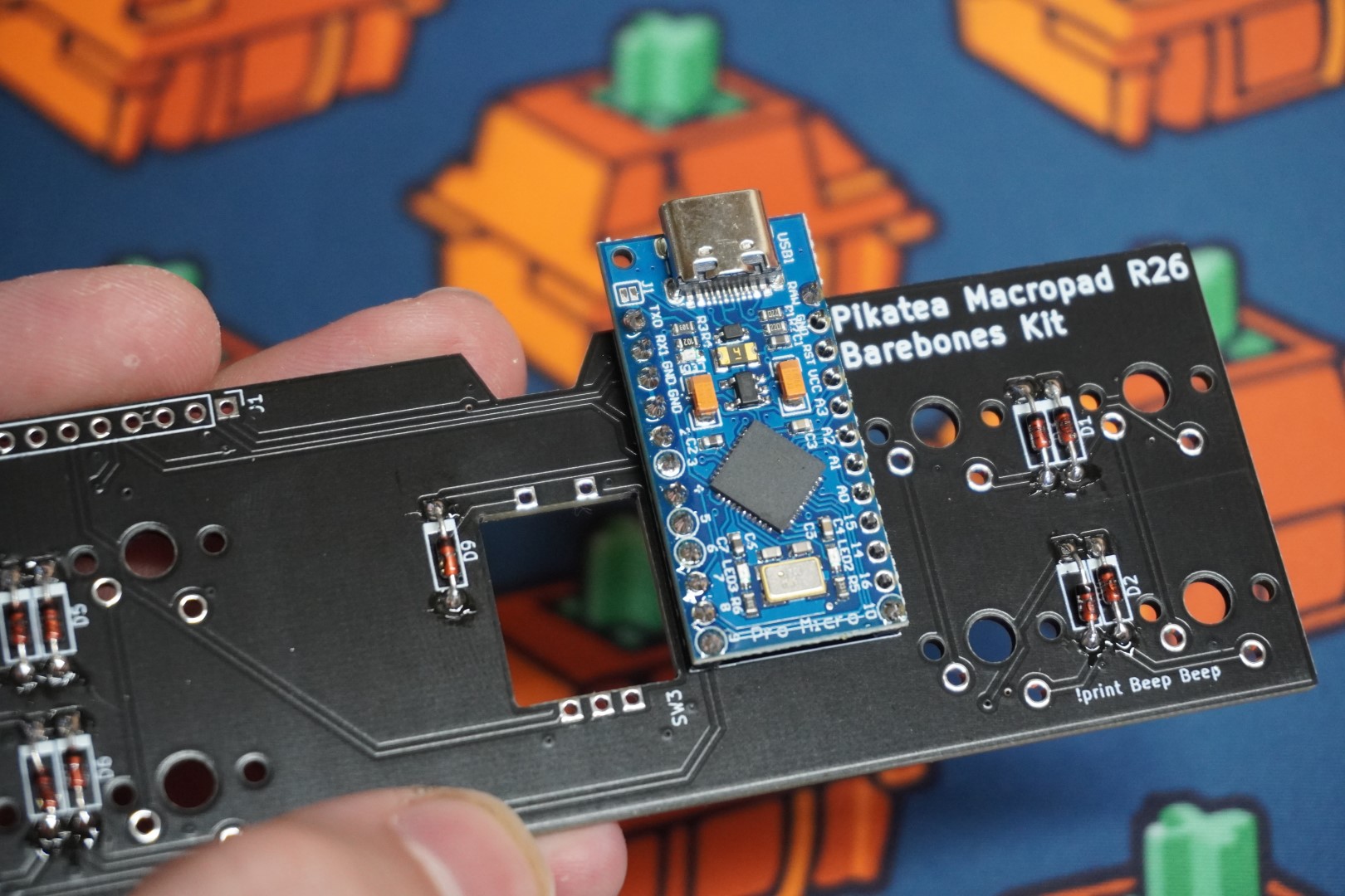
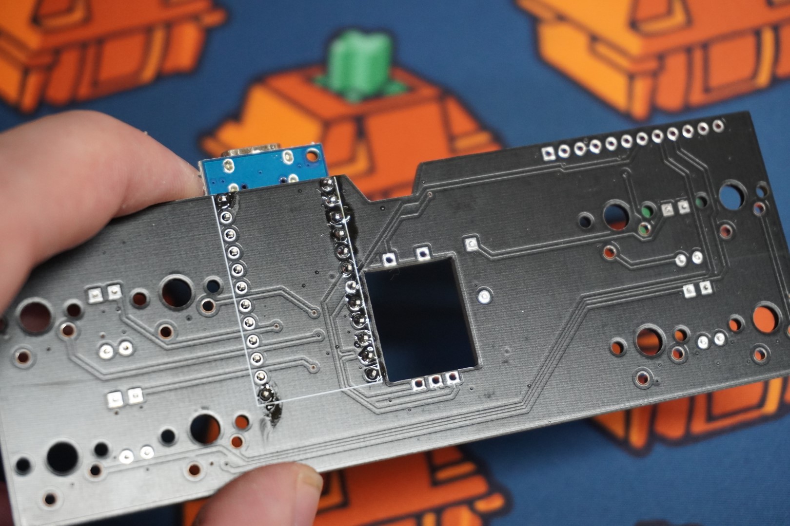
A side note: You may be wondering why we are only soldering 1 side and using diodes. This PCB is actually universal for undermounting (similar to the FK1). That means we can only use 1 side of the Pro Micro which is also why we also are using diodes.
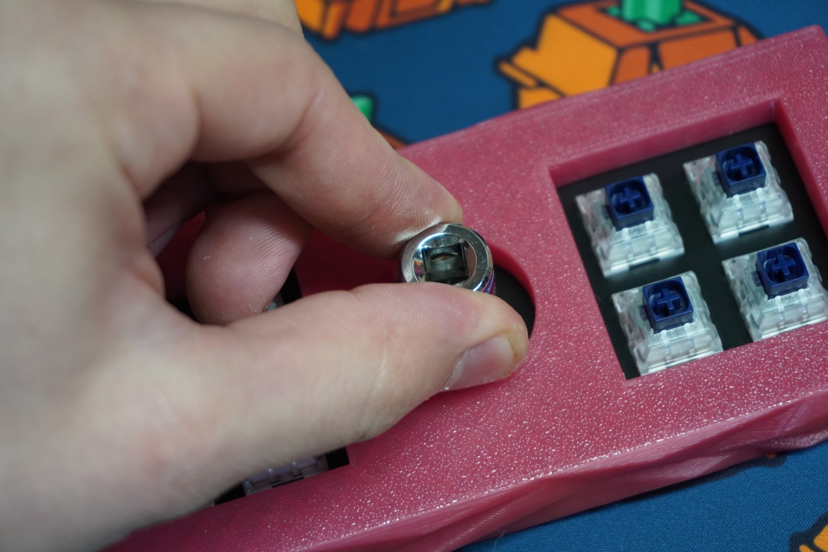
# Test The Pro Micro Again
Test it again before soldering in switches. Plug in the pro micro and make sure it is recognized in Vial as a Pikatea Macropad R26. Connect each switch pins with a metal device and verify they all work before soldering the switches.
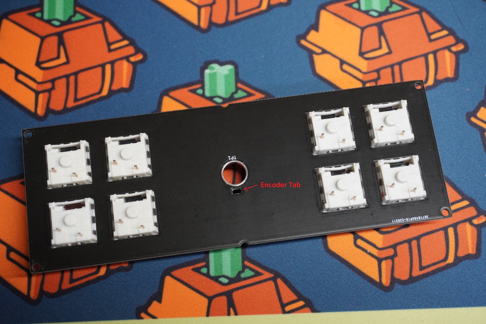
# Install The Switches
Press the switches into the FR4 plate. Make sure the orientation is correct.
It is very important that the encoder hole/tab is orientated correctly. The small square hole needs to be facing the same direction as the pins.
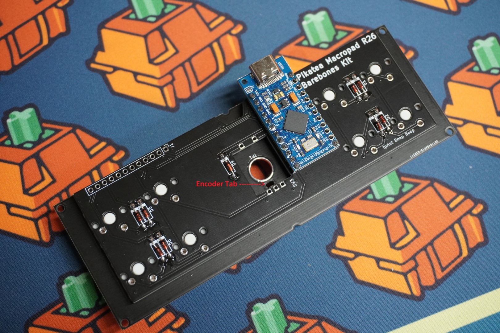
# Solder The PCB To The Plate/Switches
Again, making sure the plate is orienated correctly, place the PCB on the switches. Be sure they are flush before soldering the switches in place.
The encoder tab must be on the same side as the 3 pins as shown.

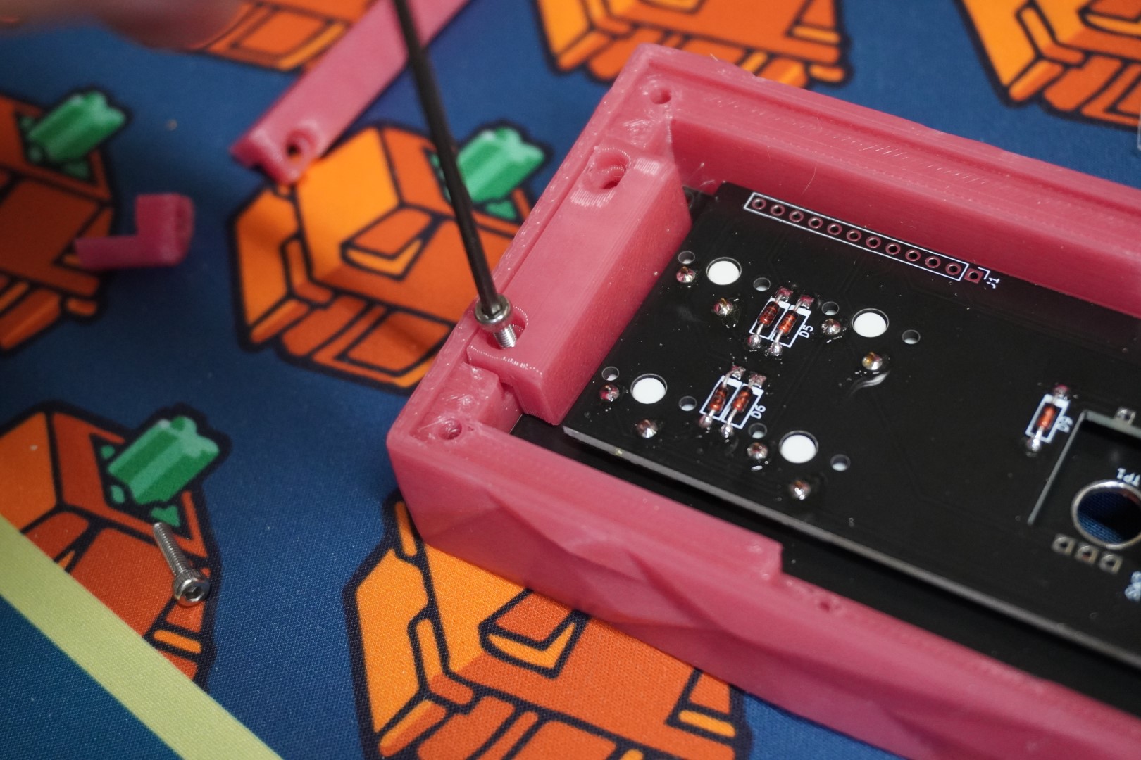
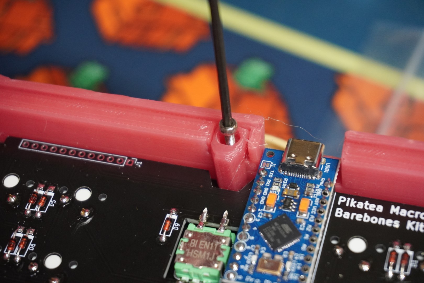
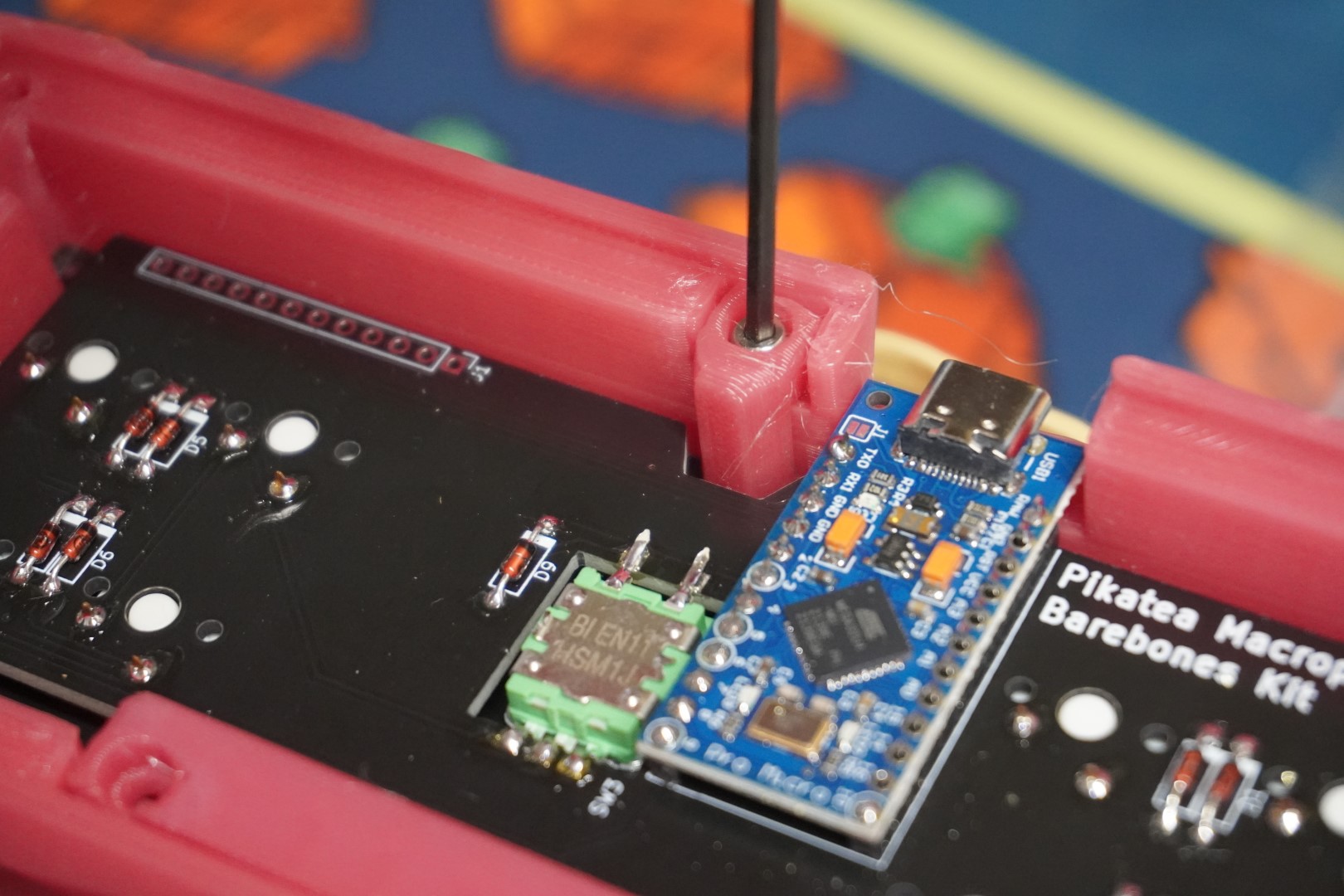
# Add The Case
With the Plate and PCB together, it's time to install the case. Use the included M2.5x10mm bolts and printed brackets to secure the plate to the case. Be sure not to over tighten, error on the side of too loose. Start with the two side brackets.
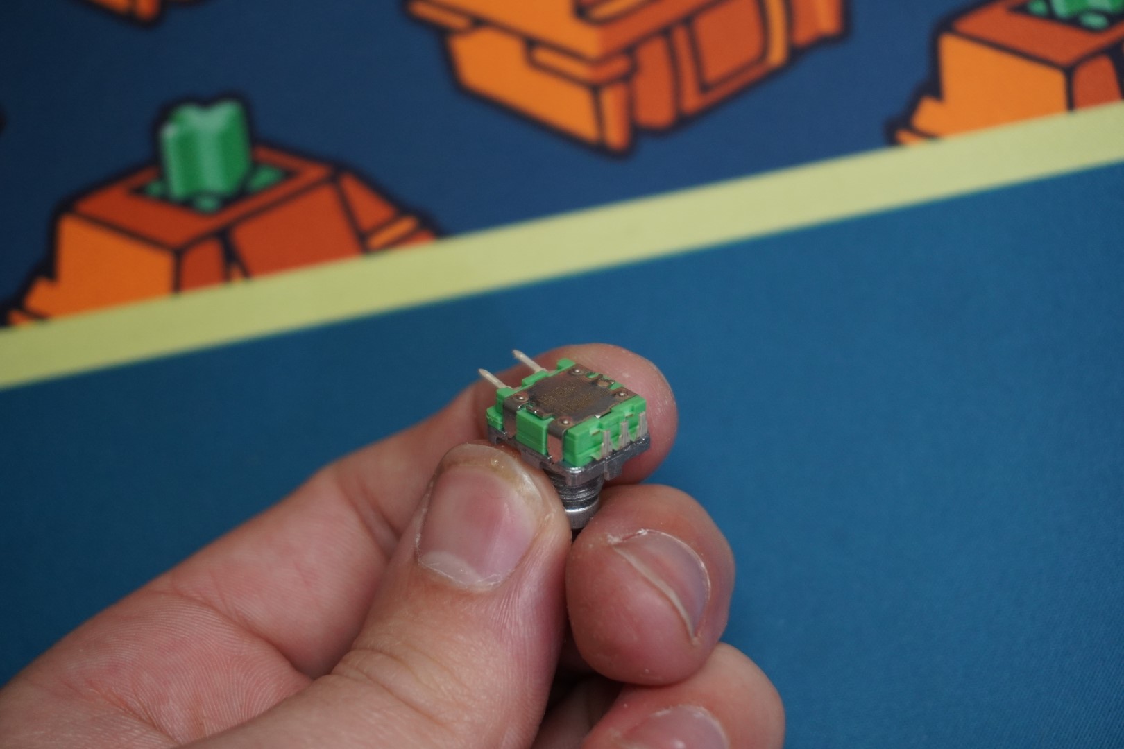
# Prep And Install The Encoder
It's a lot easier to install the encoder if parts of it are trimmed off. While this is not strickly necessary, it's recommended. Cut and bend the encoder as shown.
Place the encoder in the plate/PCB and secure it with the included hardware. Do not fully tighten the encoder until AFTER soldering it in place. Adjust the encoder so that it is centered and straight.
Use the roll of tape to hold macropad so that it does not wobble while soldering. Start with the 2 button pins and move to the A, GND, and B pins. You can bend the A, GND, and B pins if you feel it is necessary.
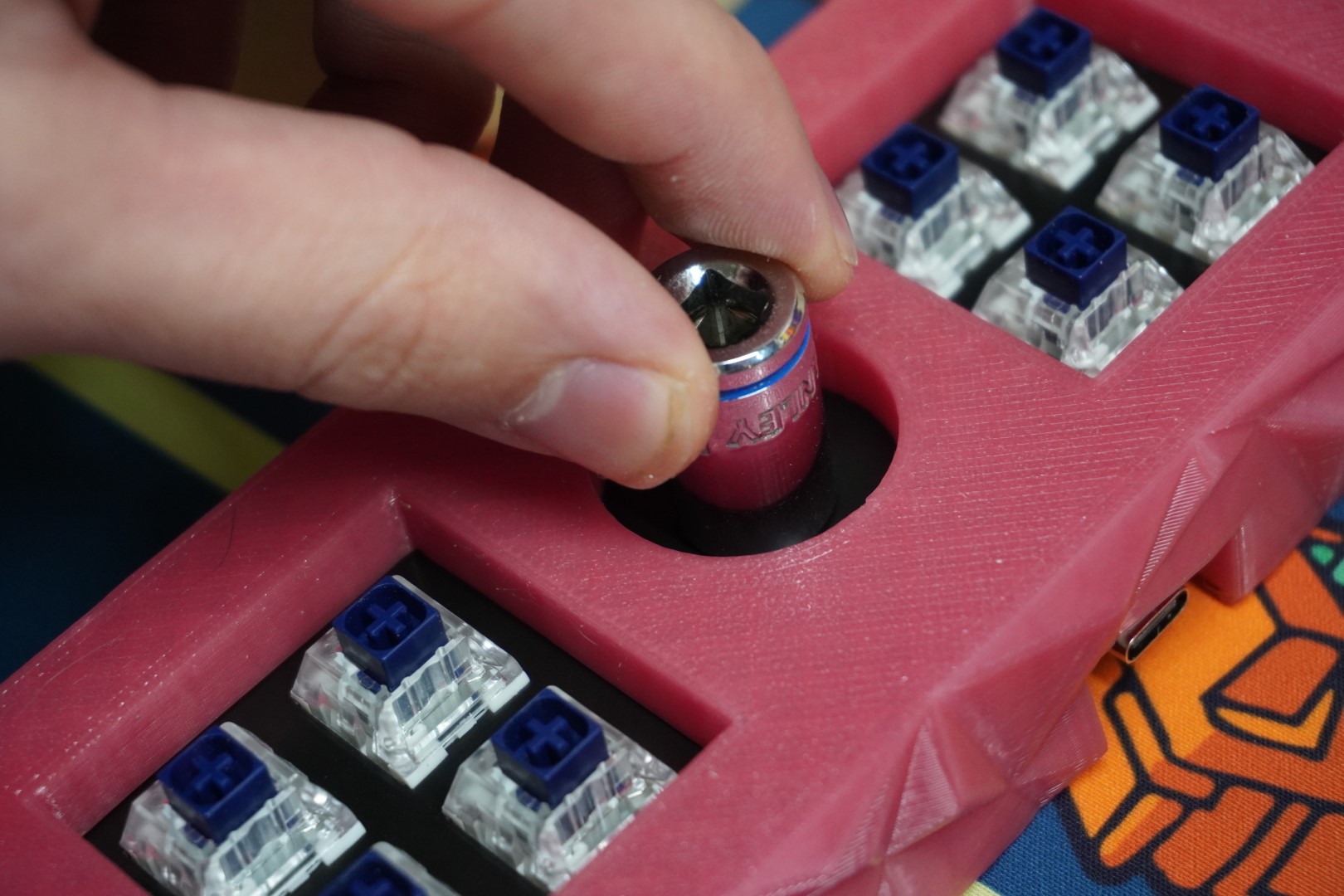
Fully tighten the encoder. We recommend hand tightening with a 10mm socket.
# Finish Case
Add the rest of the brackets. Again, be sure not to over tighten. Error on the side of too loose.
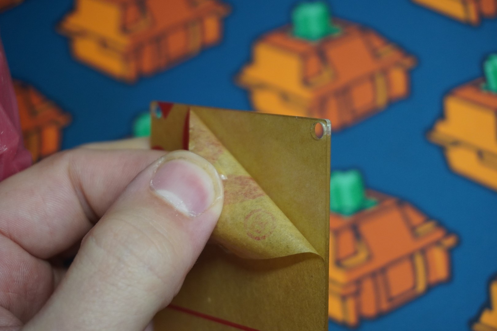
# Add The Backplate
Install the acrylic or 3D printed backplate using the M3x8mm button head screws. Get each screw started before tighting them down. Again, Error on the side of too loose.
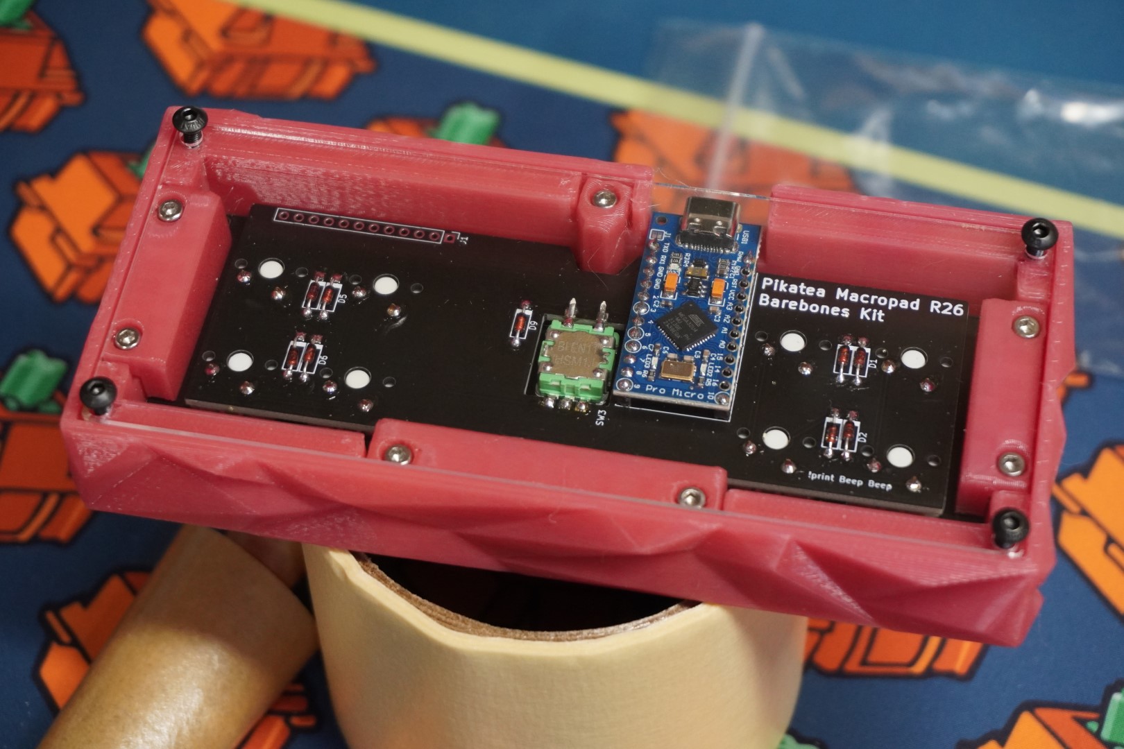
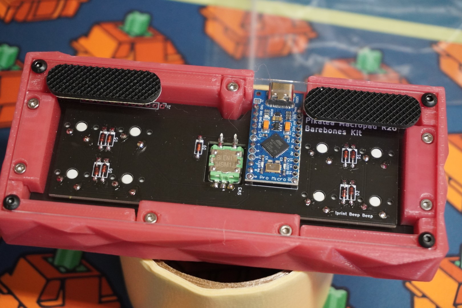
Add the rubber feet where you'd like.
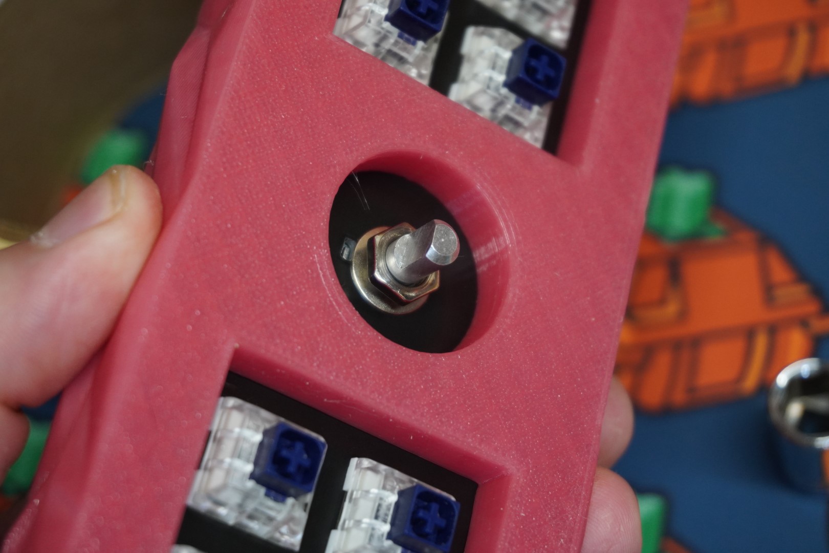
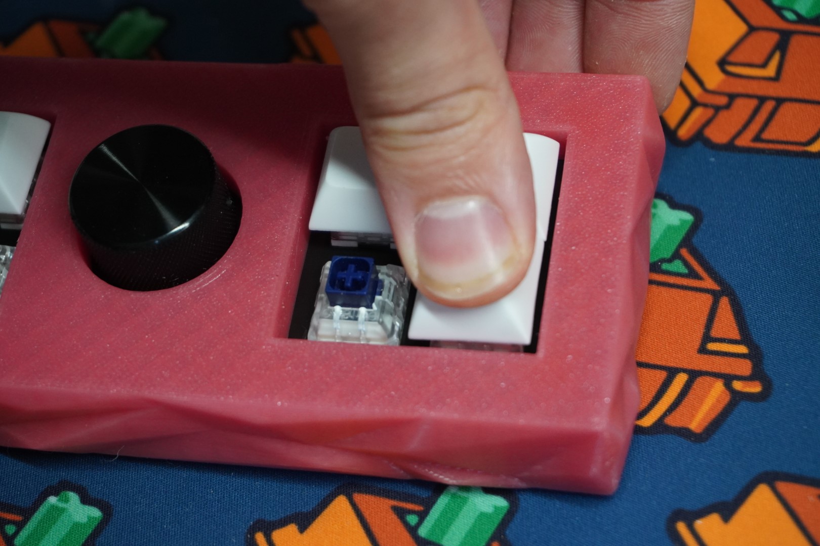
# Add Knob and Keycaps
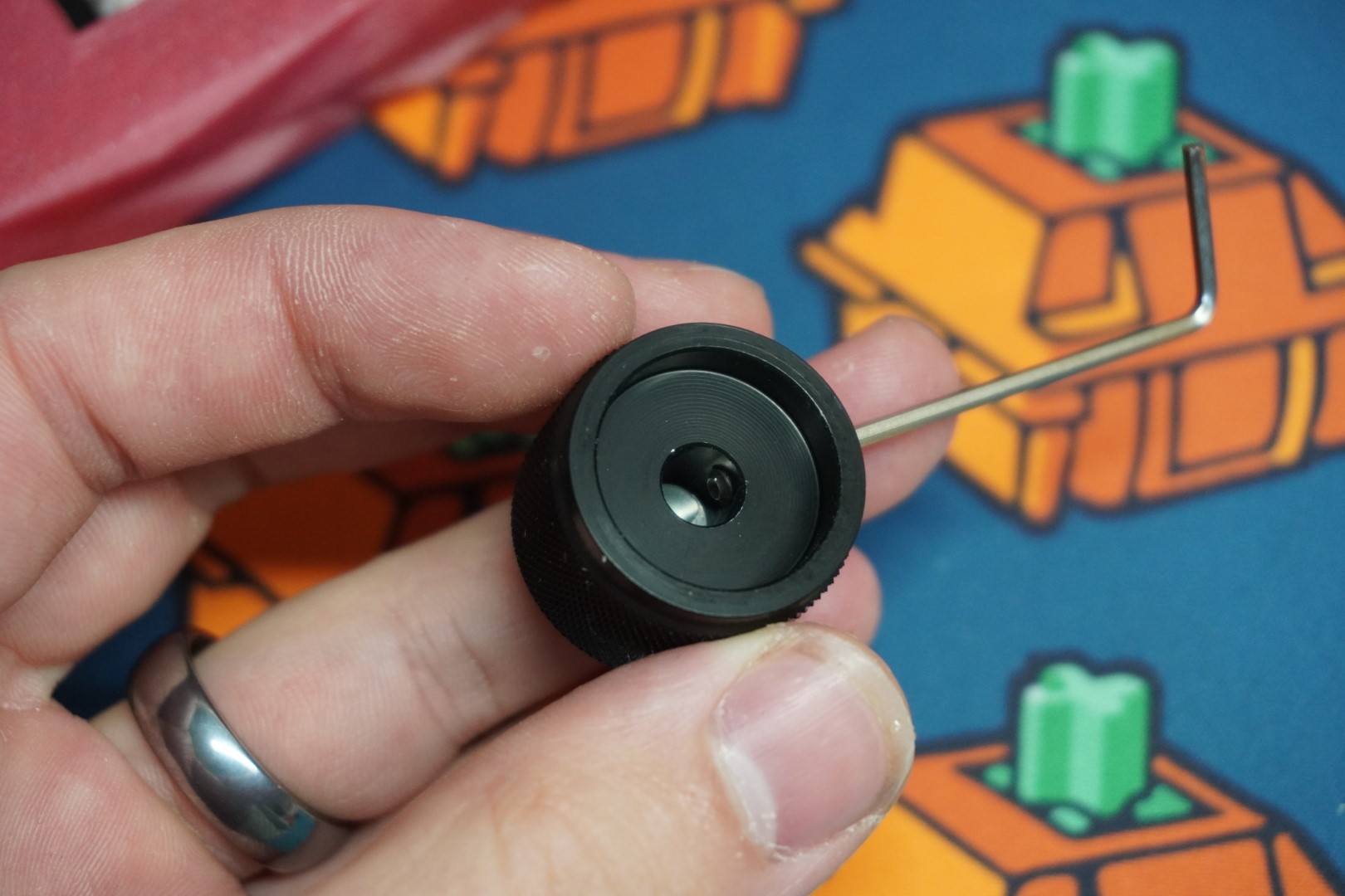
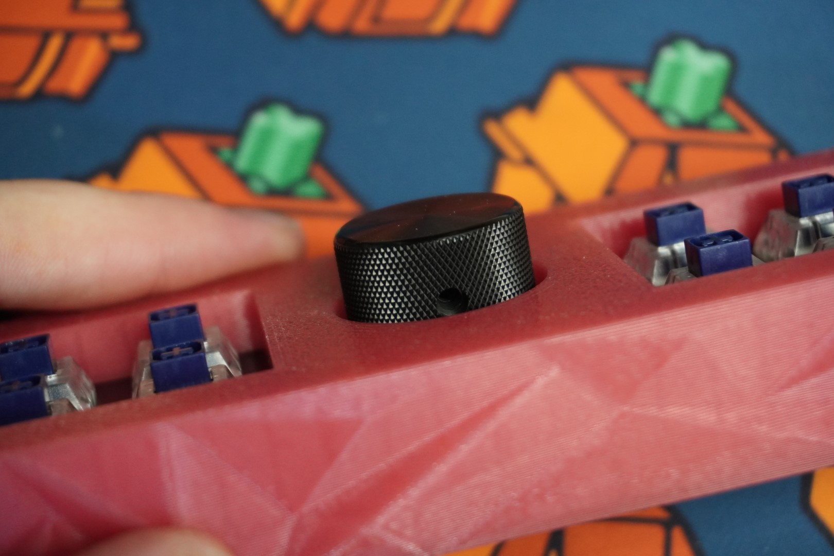
The knob can be installed in a few different ways. Most knobs will have a setscrew. Be sure the setscrew screws into the flat part of the encoder shaft. Some 3D printed knobs just slide on with no setscrew required.
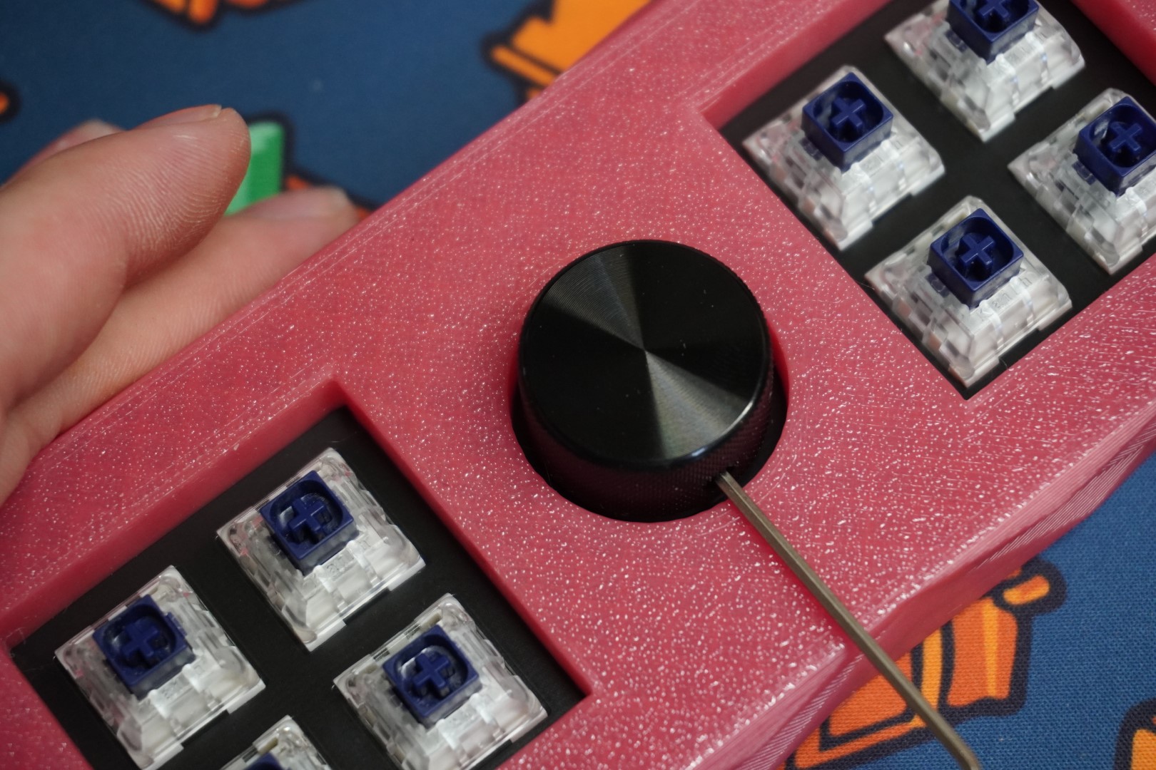
Finally, add the keycaps!
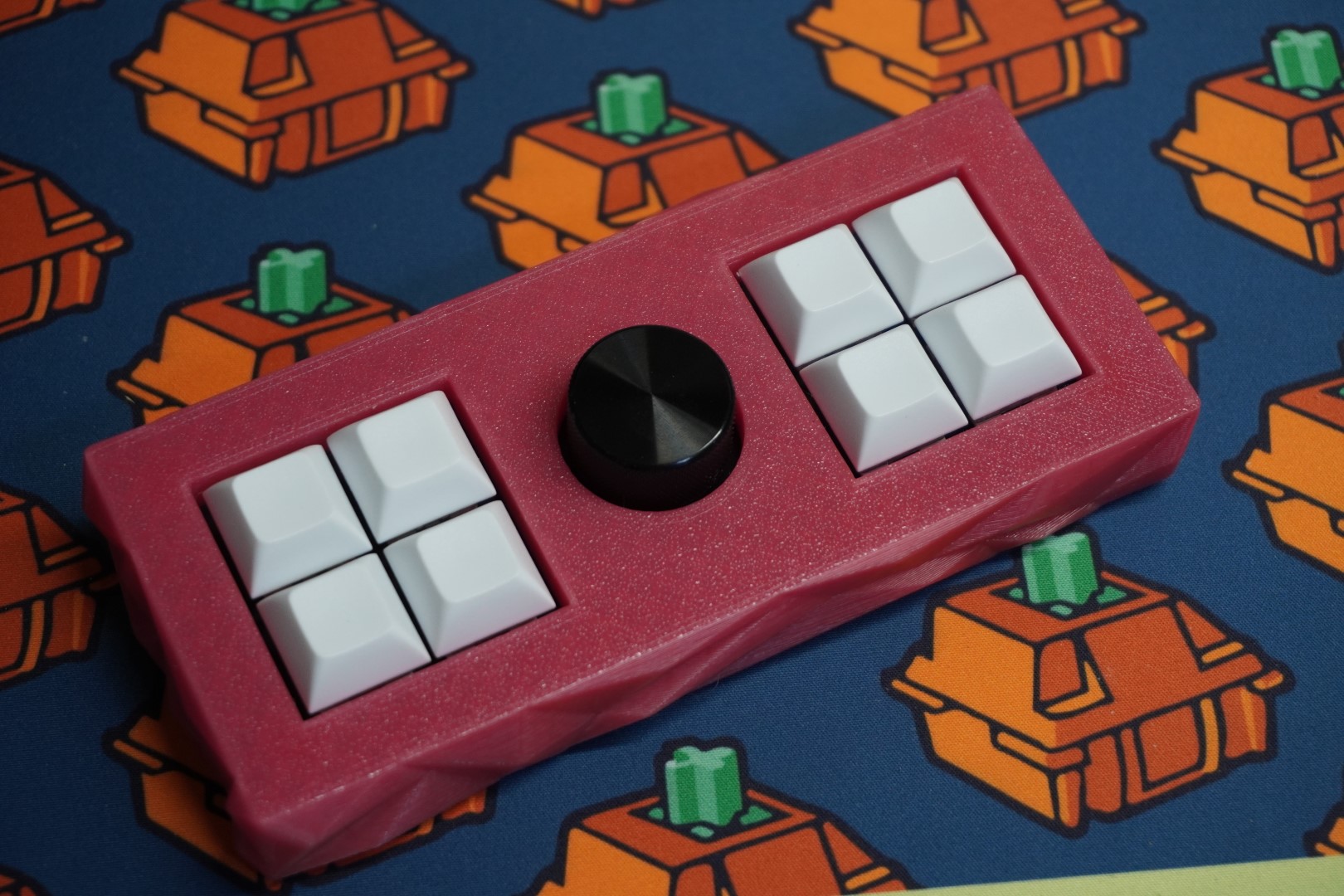
# Done
That's it! You've built the R26. Head over to the programming for instructions on programming and usage