# Cerberus Assembly Guide
This guide uses a few photos from other keyboards but the assembly process remains the same. Ask on discord if you have any questions.
To complete this keyboard, you'll need choc switches and choc stabilizers
# Flash the MCU
It's important to flash the MCU before starting to make sure it works.
- Download the .uf2 file for the device from the firmware list.
- While holding the boot button, plug the MCU into the computer.
- Drag the .uf2 file into the new drive that shows up. Confirm the device shows up in VIAL (opens new window) after it disconnects and reconnects.
# Solder the Diodes
- Bend a diode and insert it into the PCB being careful it is the correct orientation. The black bar on the diode matches with the thicker white bar on the PCB.


- After the diode is inserted, bend the leads outwards so it stays in place. Repeat steps 1 and 2 for each diode.
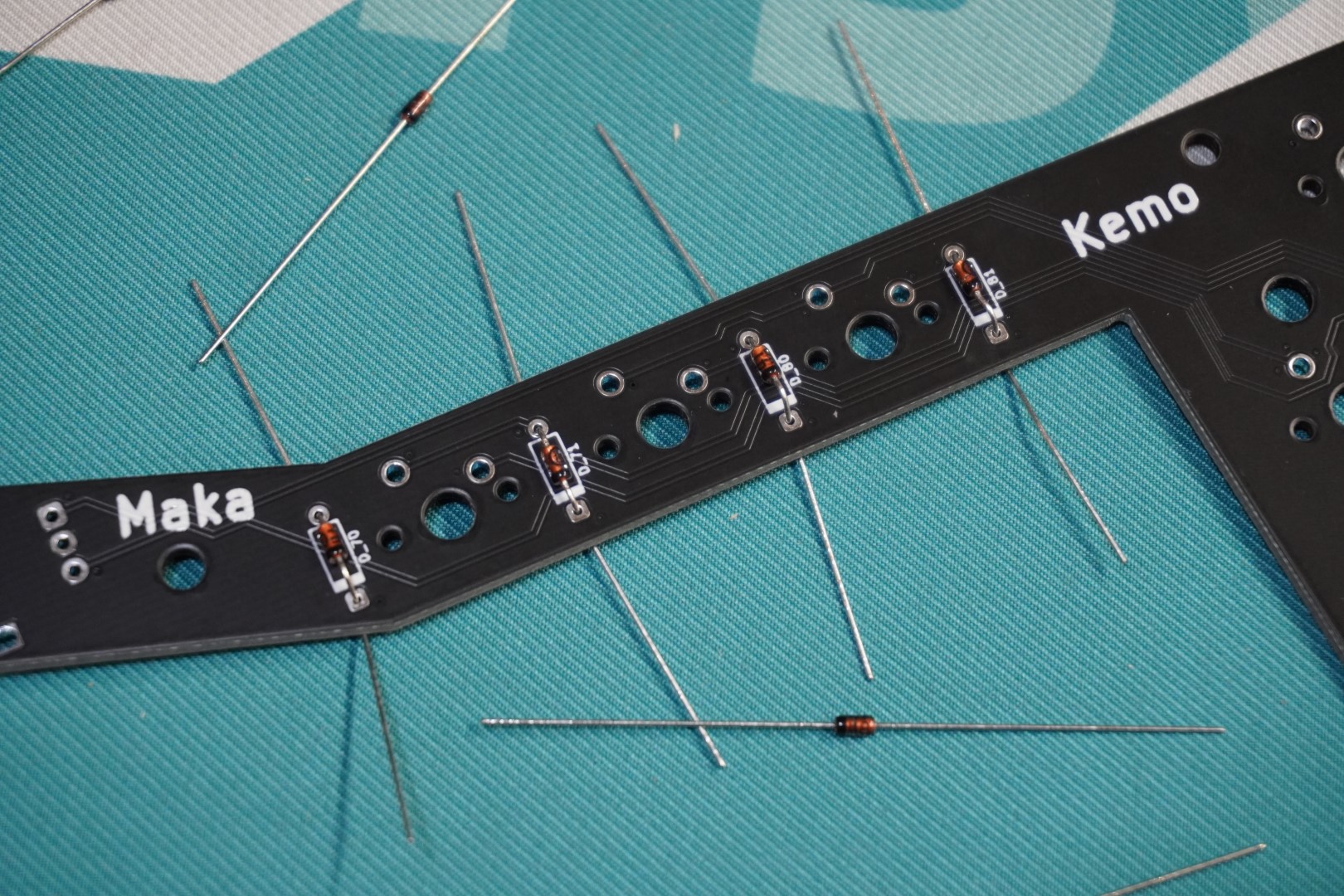
- With each diode in place, Solder them to be permanently secured.

- Bend the diodes legs straight and use flush cuts to them off. Be careful not to scratch the PCB when doing this.


# Important Note
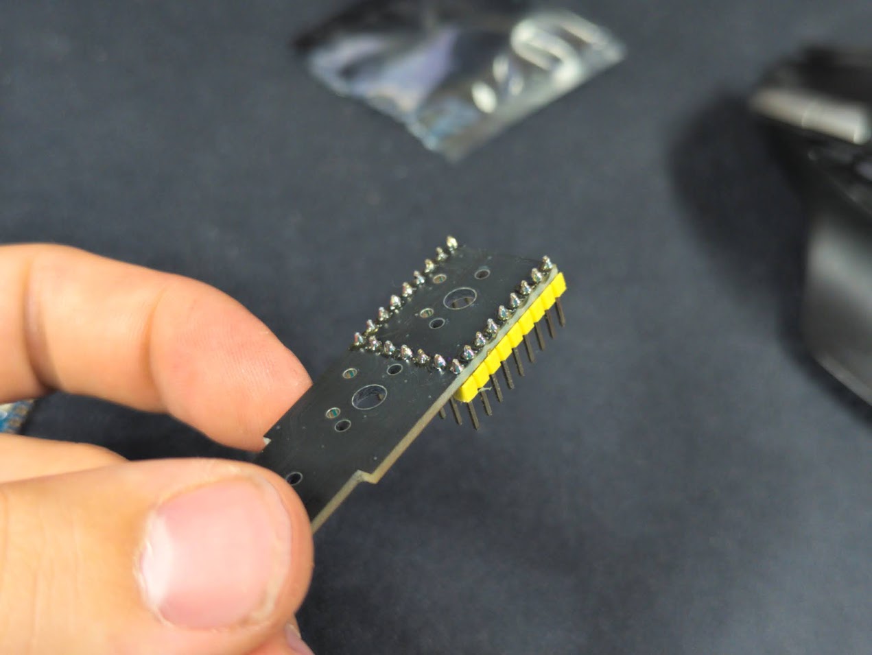
# Trim The Headers
The headers need to be trimmed or the case will not fit. The image shows different sized headers than the kit but the process is the same.
- Cut the longer side of the headers in half as shown. It doesn't have to be precise.


# Solder The Headers
The following images shown are for a different keyboard but the steps still apply.
The first step is to solder the headers to the PCB. ONLY the headers.
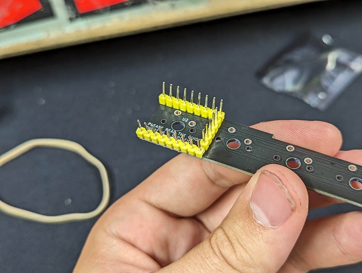
Solder only the headers to the PCB so that you end up with the following. DO NOT SOLDER THE MCU TO THE HEADERS YET
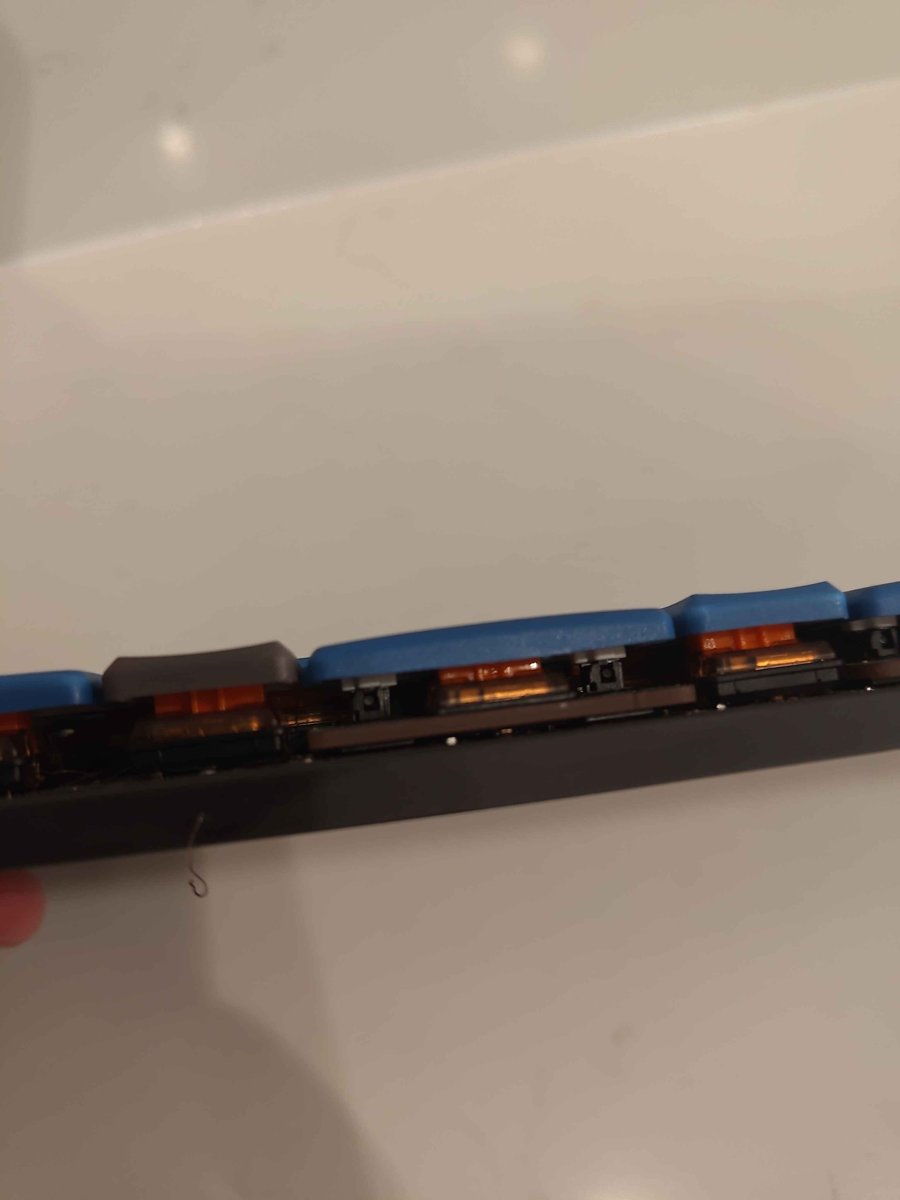
# Stabilizers and Switches
Solder each low-profile choc switch to the PCB. Be sure to include the stabilizers for the larger keys.
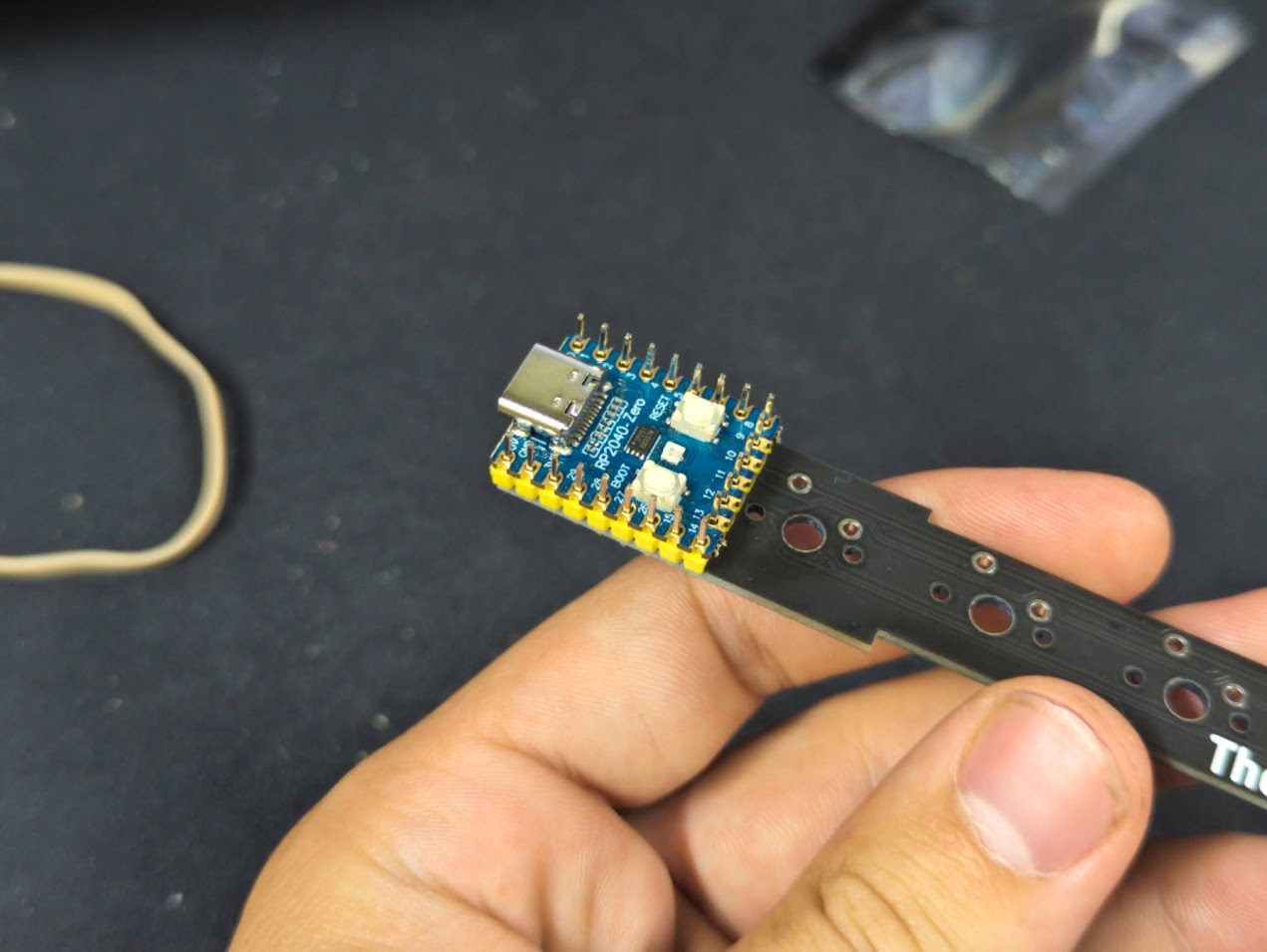
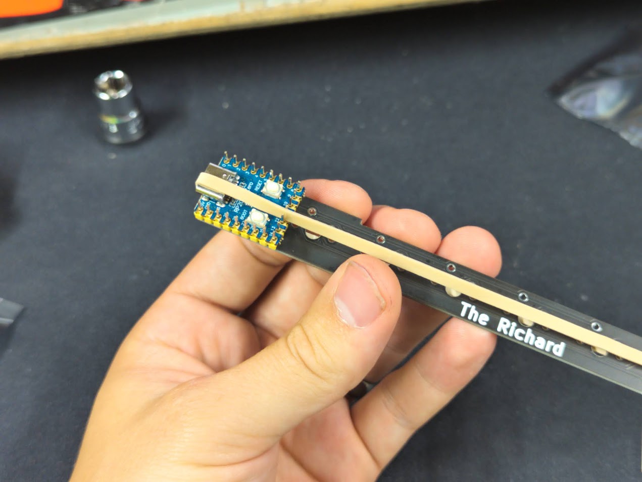
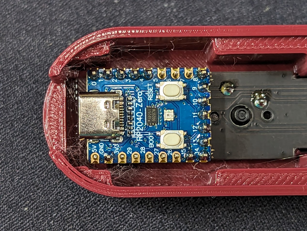
# Solder the MCU
Solder the MCU to the headers. This is the last of the critical order steps. Solder each pin.
# Finish Assembly
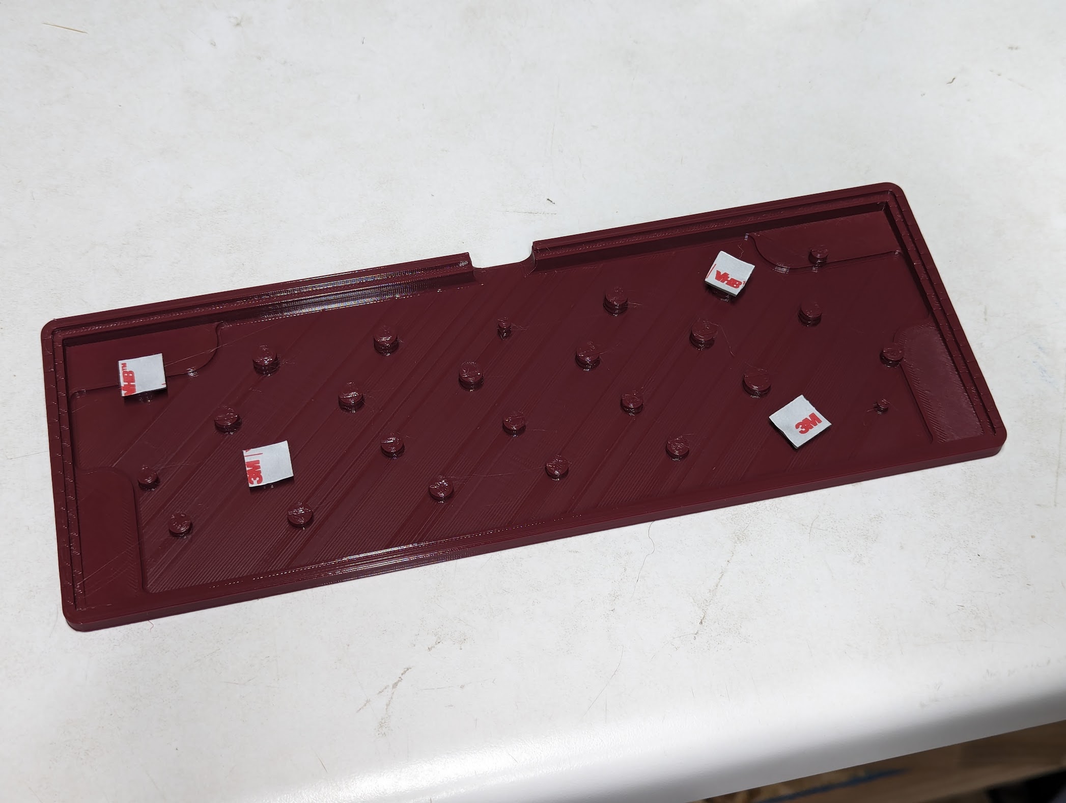
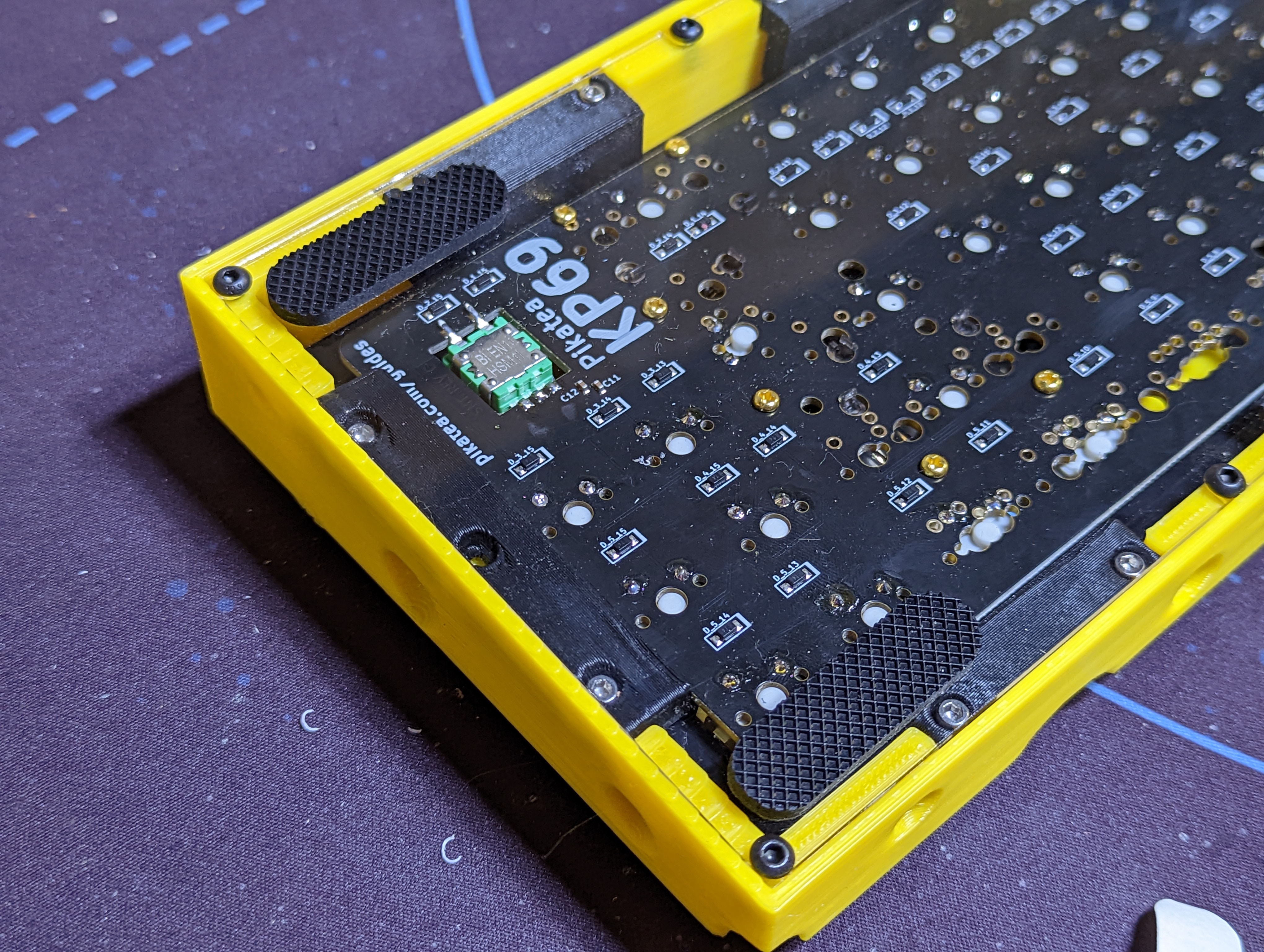
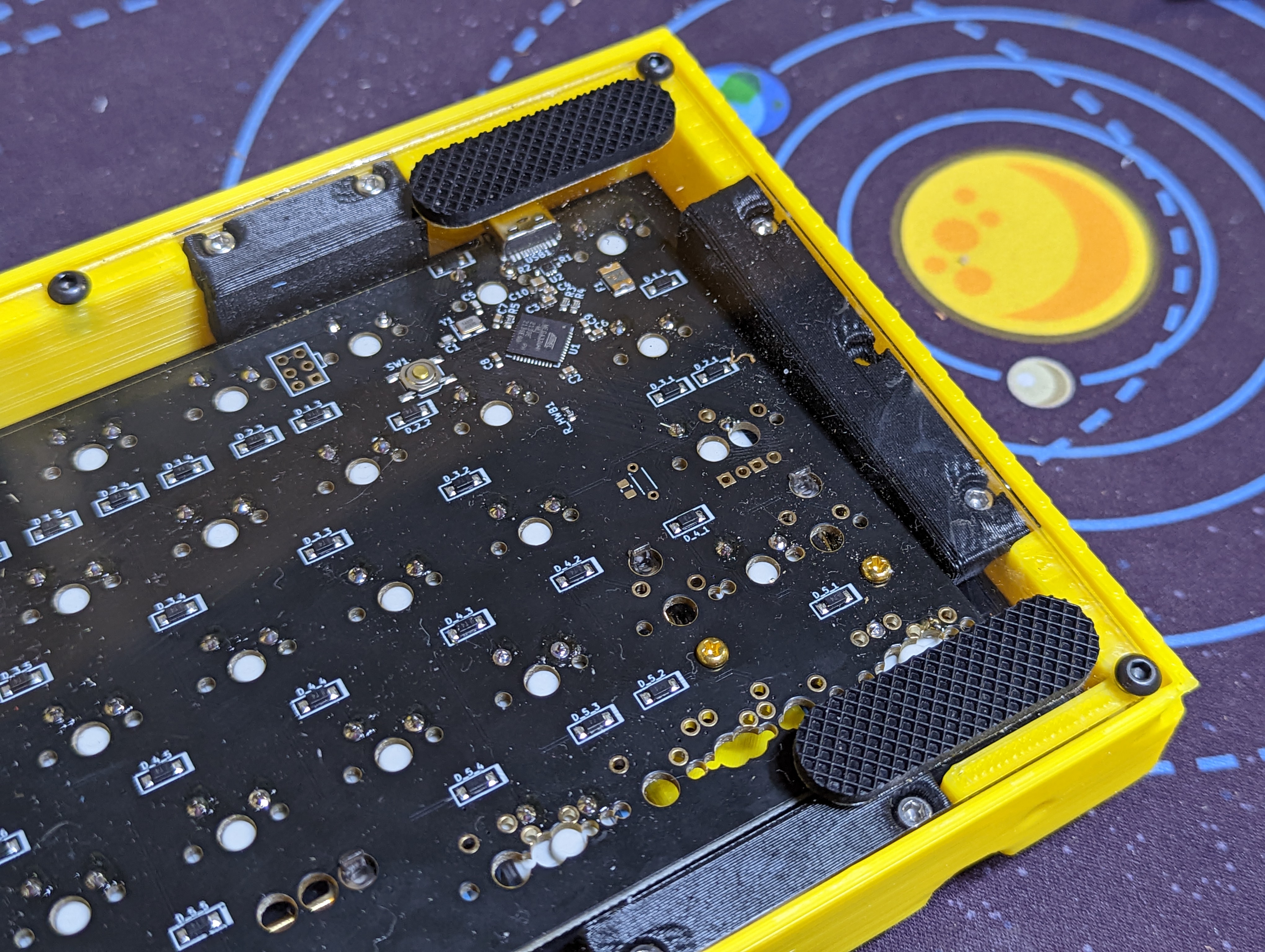
With the PCB and plate put together, it's time to assemble the remaining components and complete the keyboard. Cut strips of double sided tape and plate on the mounting tabs as shown. Peel back the tape to reveal the sticky section. Place the completed keyboard PCB assembly onto the case. It may take a few days for the adheasive tape to fully bond.
# Add Keyboard Feet
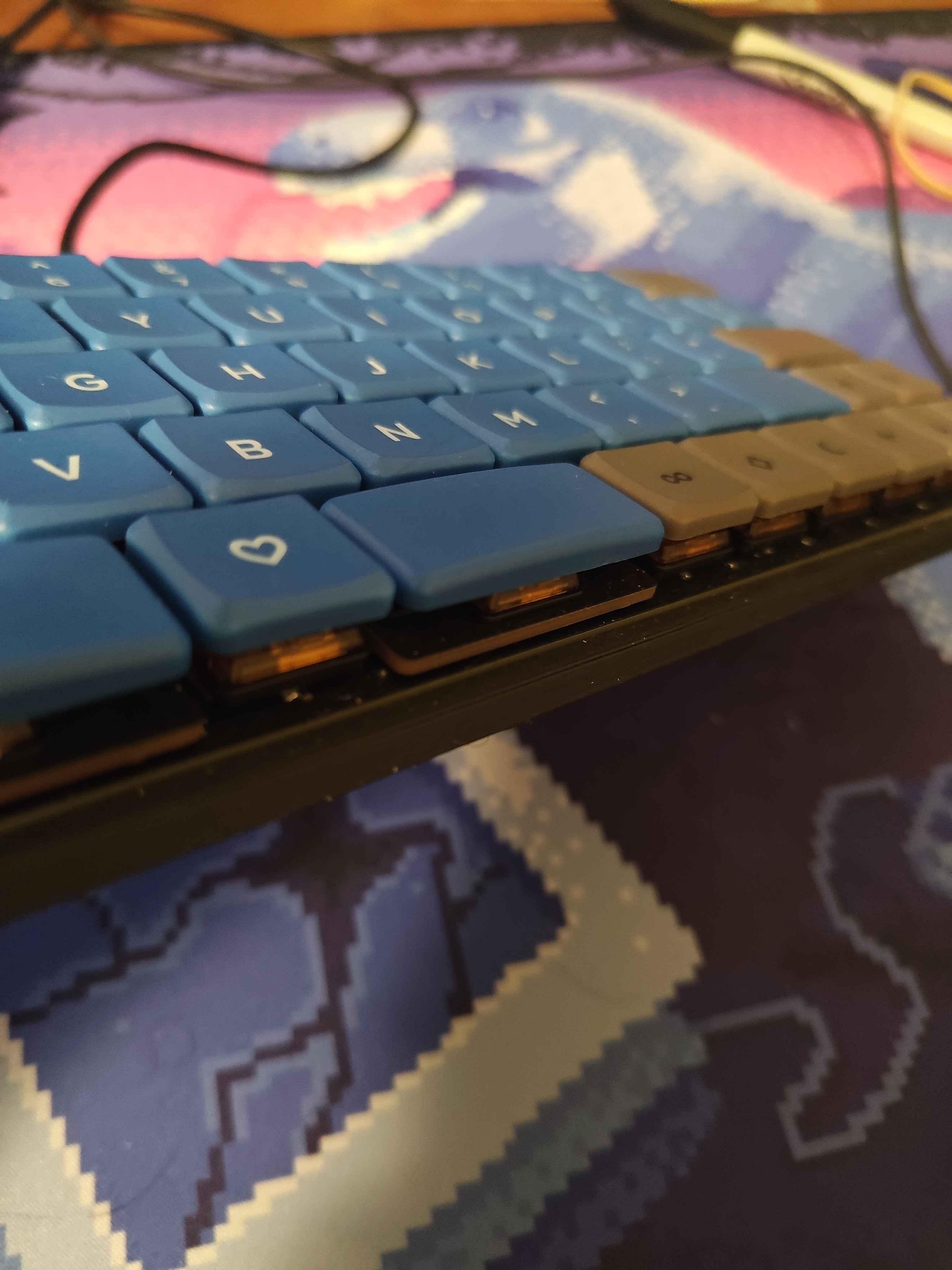
# Add keycaps and knobs
# That's it!
- Celebrate. It's required.
Check out the programming guide to learn more about how to use your device.