# Pikatea Keyboard KP69 Assembly Guide
Congratulations on receiving your Pikatea Keyboard KP69 Kit. This guide will walk you through the assembly process. Please email support or ask on Discord if you have any questions.
# What's in the Box

- (1) 3D printed case
- (1) FR4 Top plate
- (1) Circuit board
- (1) Acrylic backplate
- (4) Keyboard feet
- (1) Knob
- (1) Rotary encoder with hardware (washer and nut)
- (1) Allen wrench (1/16in and 2mm)
- (2) Hardware
- (1) Set of printed L brackets
- (1) Set of gaskets
# Gather Required Materials
You will need everything that comes with the kit as well as a few other items. Those additional items include:
- Soldering iron and solder
- Flush cut snips (recommended), metal cutters, or wire cutters.
- Screw driver
- Pliers, adjustable wrench or a 10mm socket
Now that you have everything you need, lets get started!
# Install the gaskets into the case
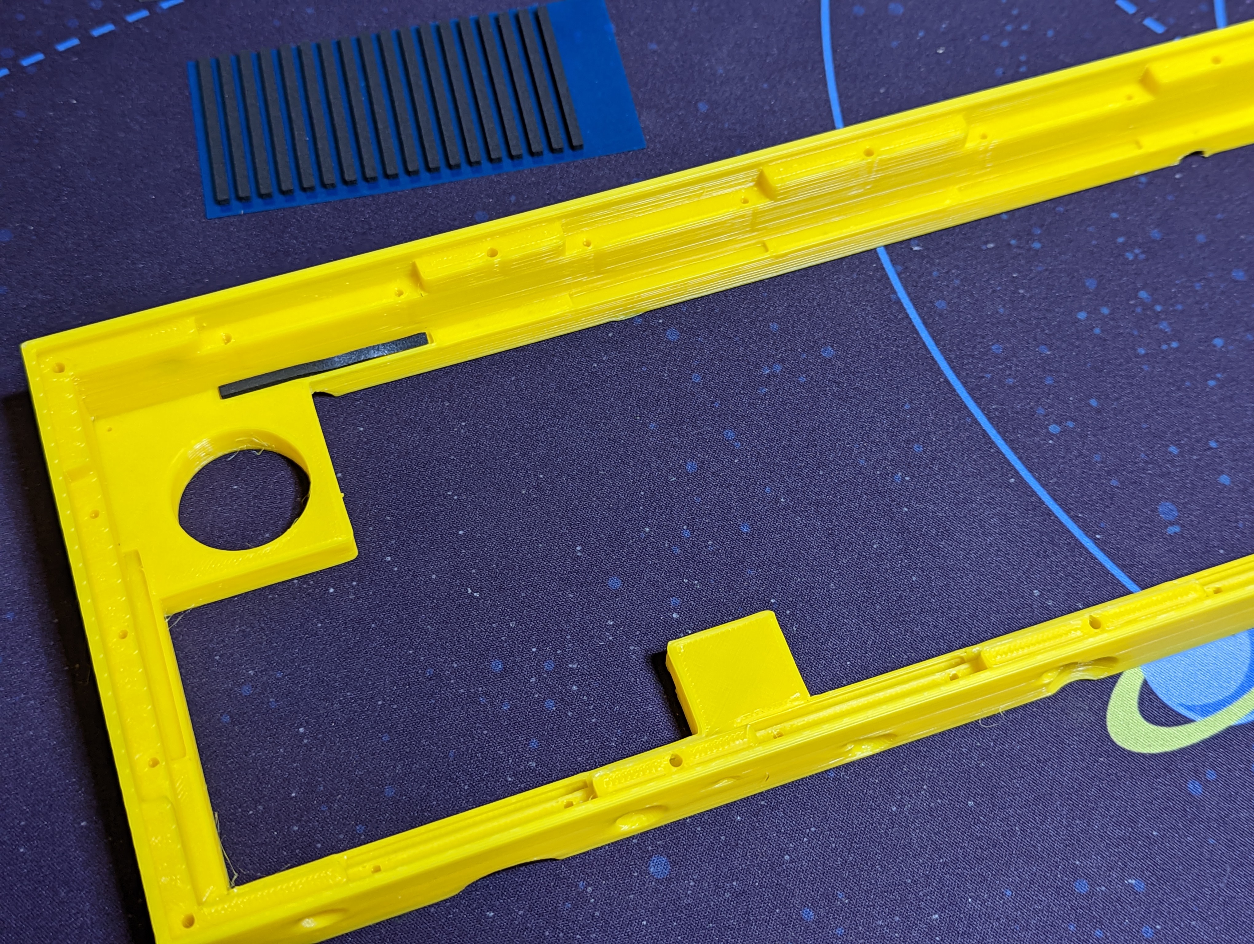
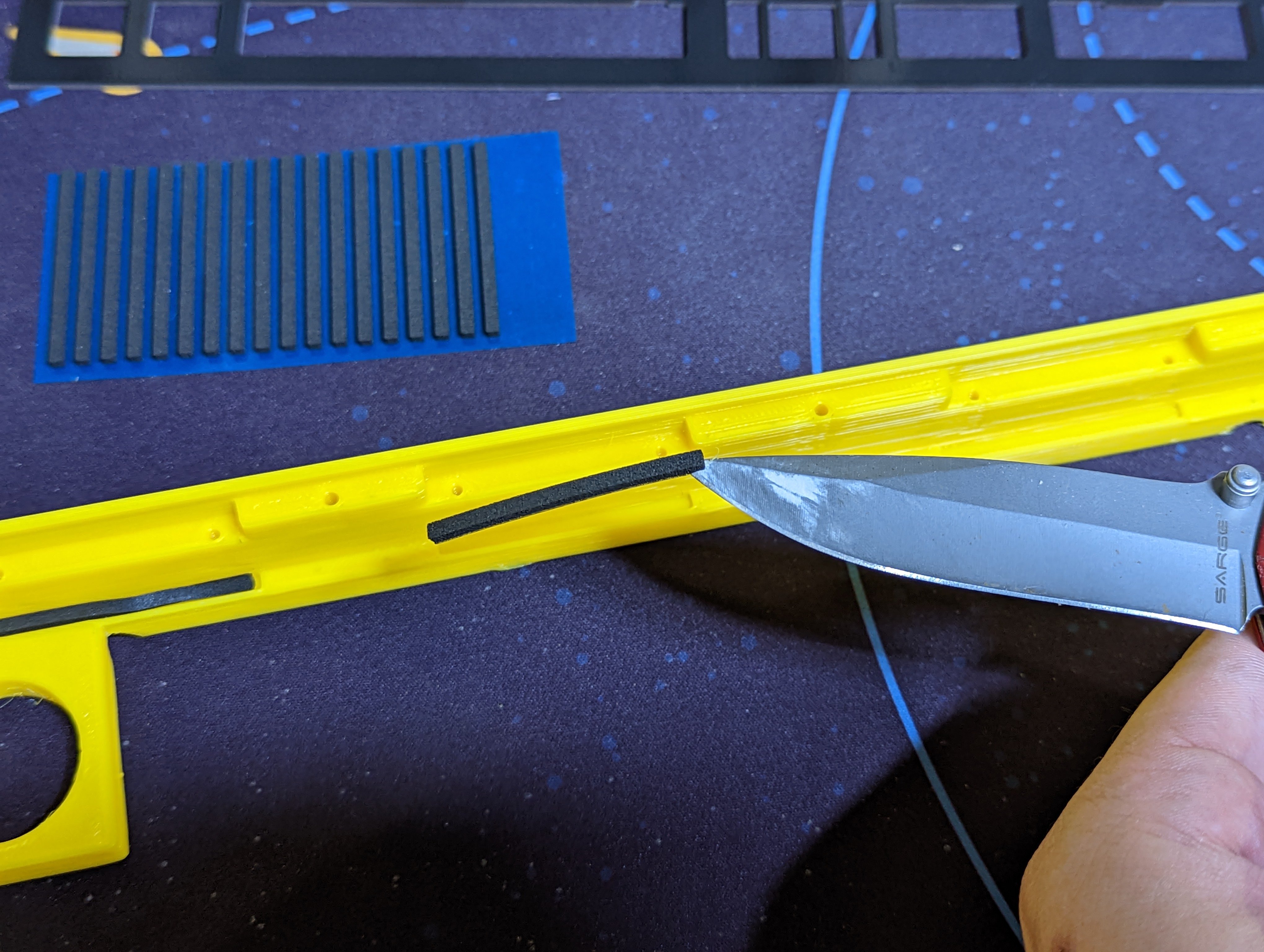
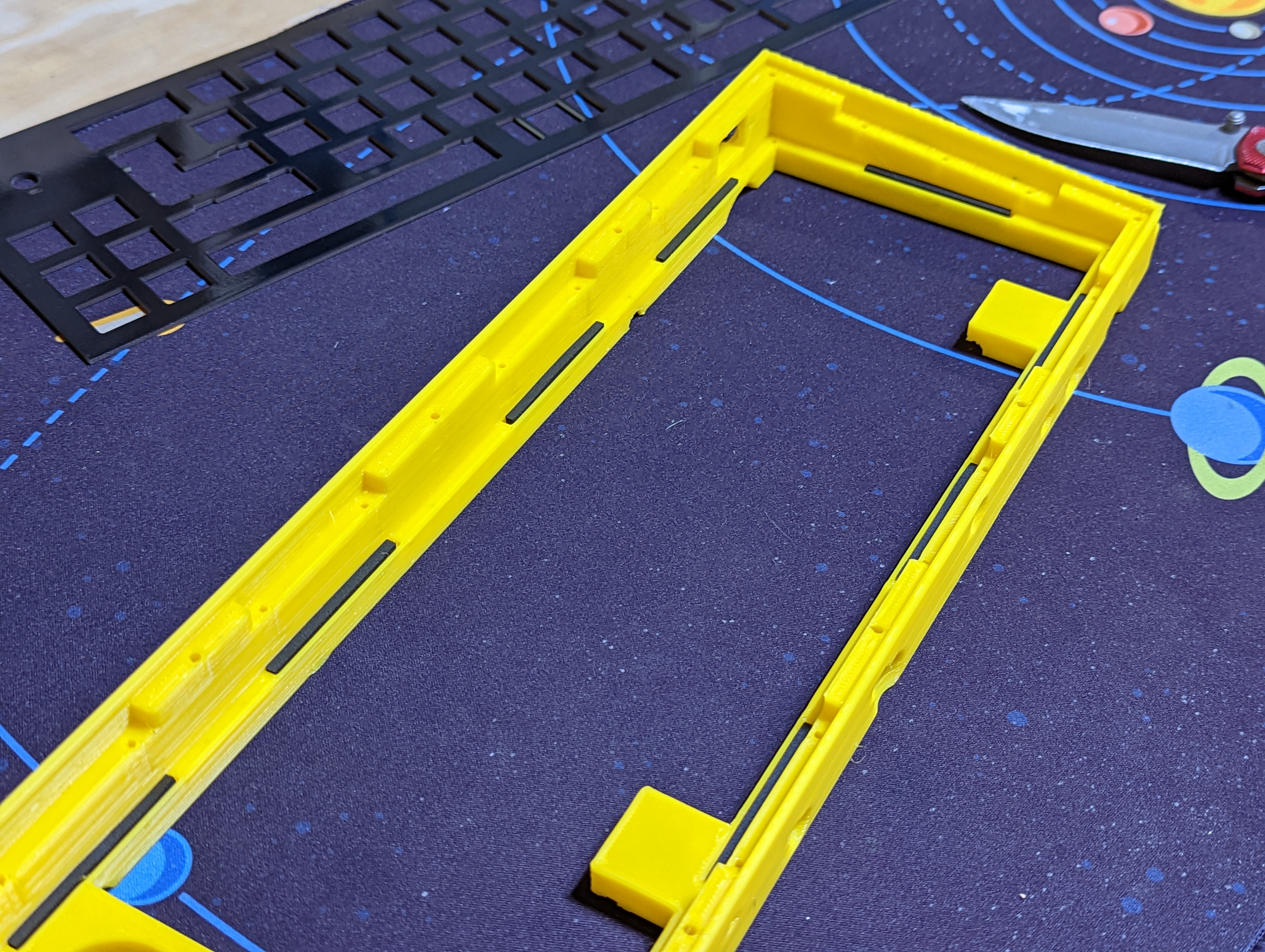
Begin by installing the included gaskets into the slots in the underside of the case as shown. It helps to use a knife to assist with holding the gaskets while using your other hand to guide it into place.
# Test the PCB
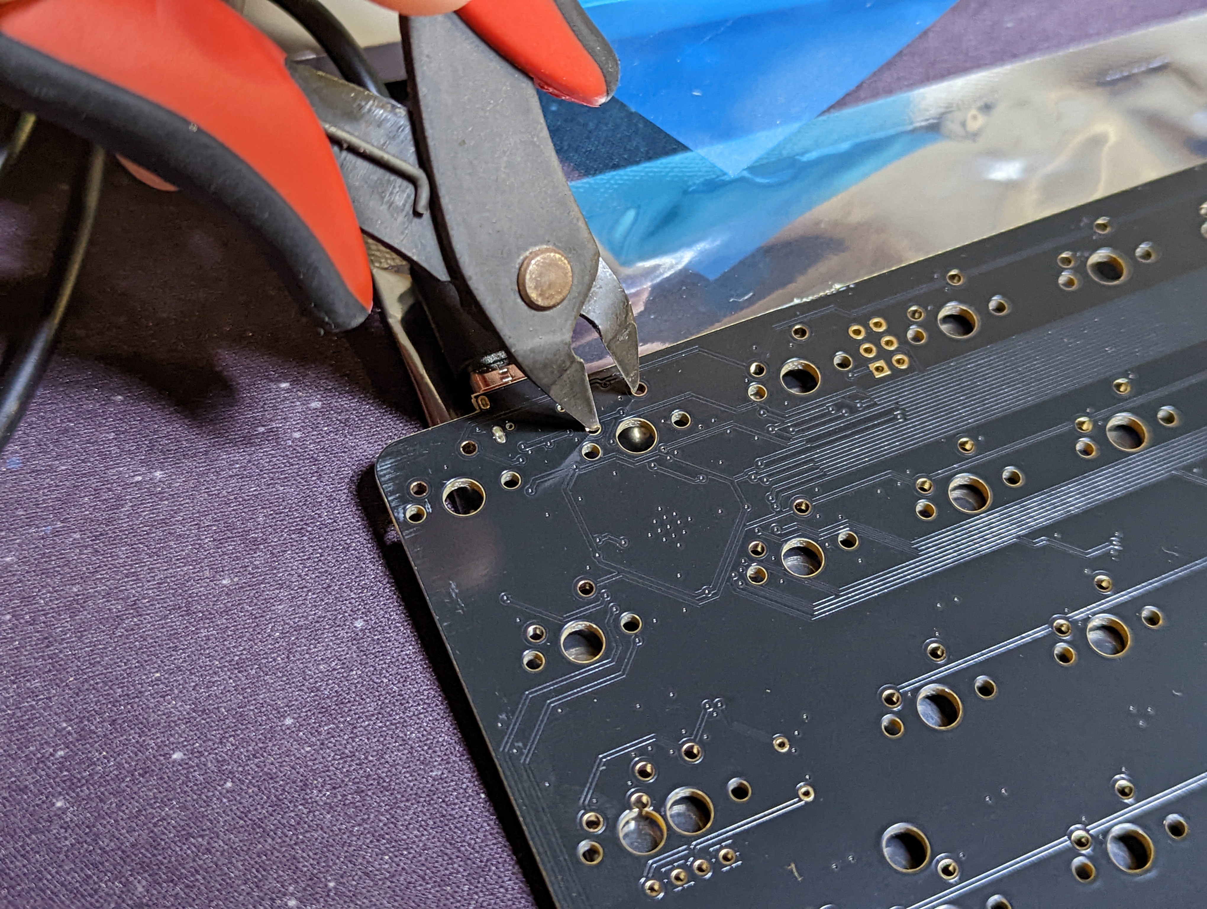
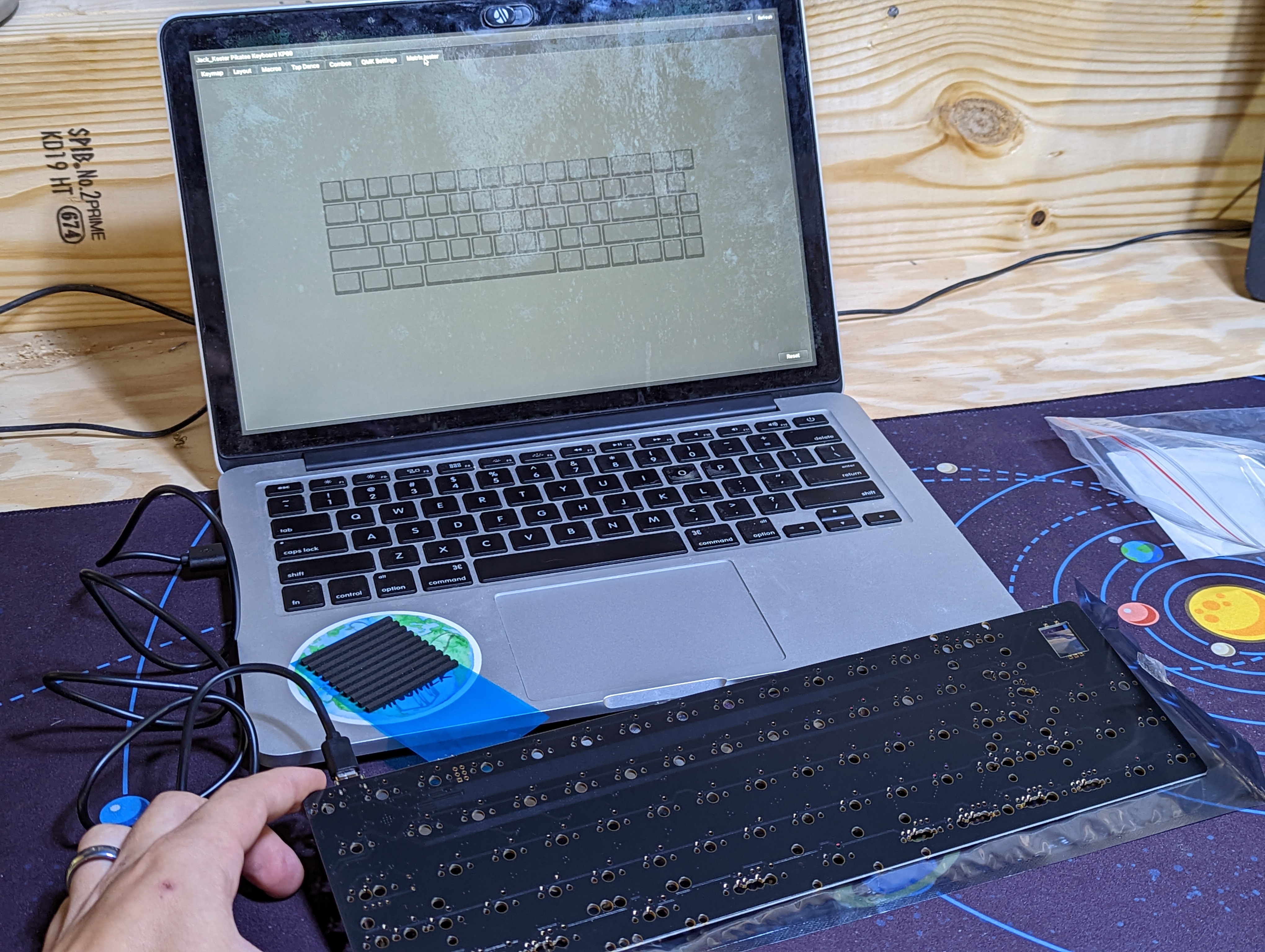
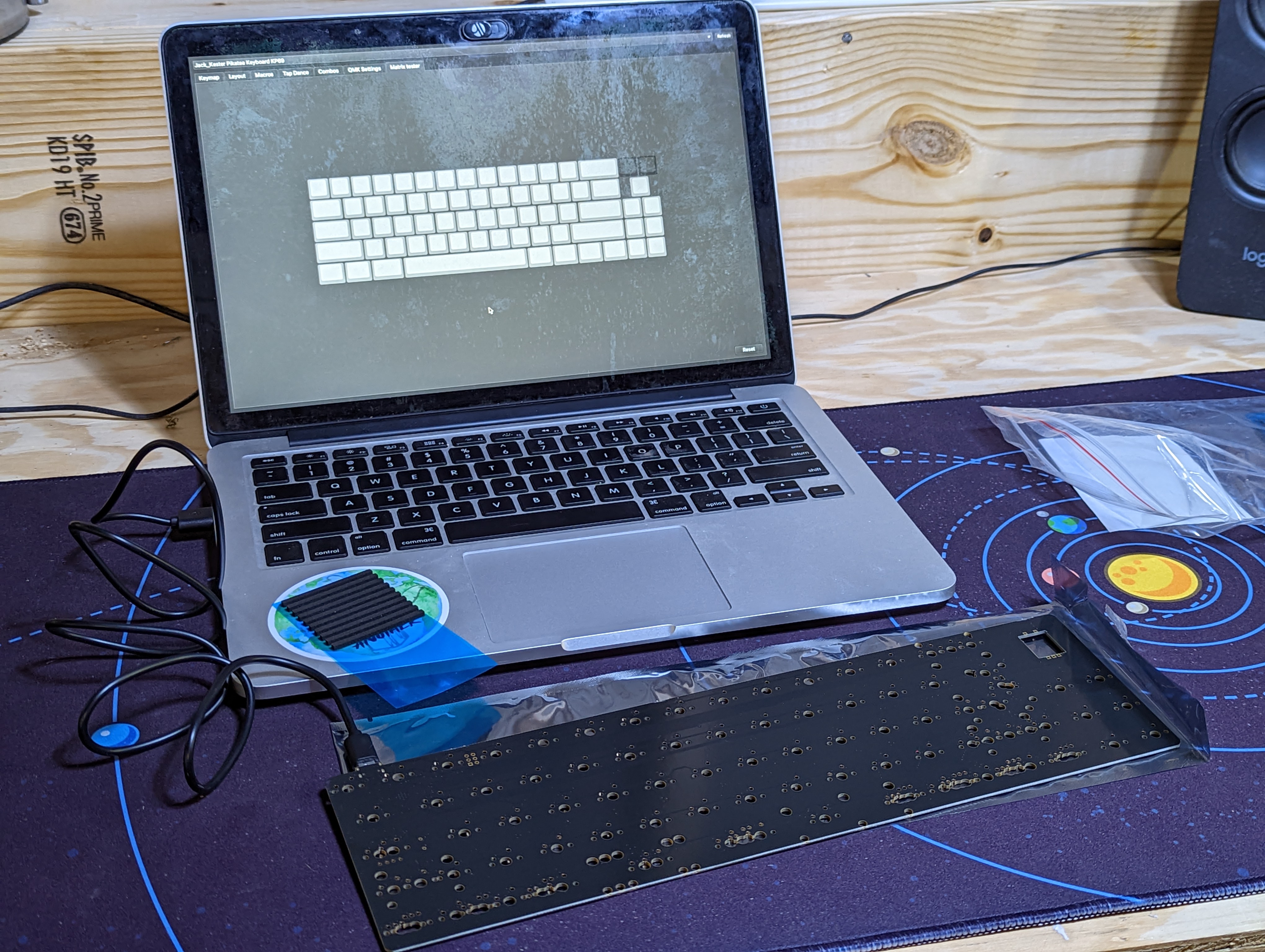
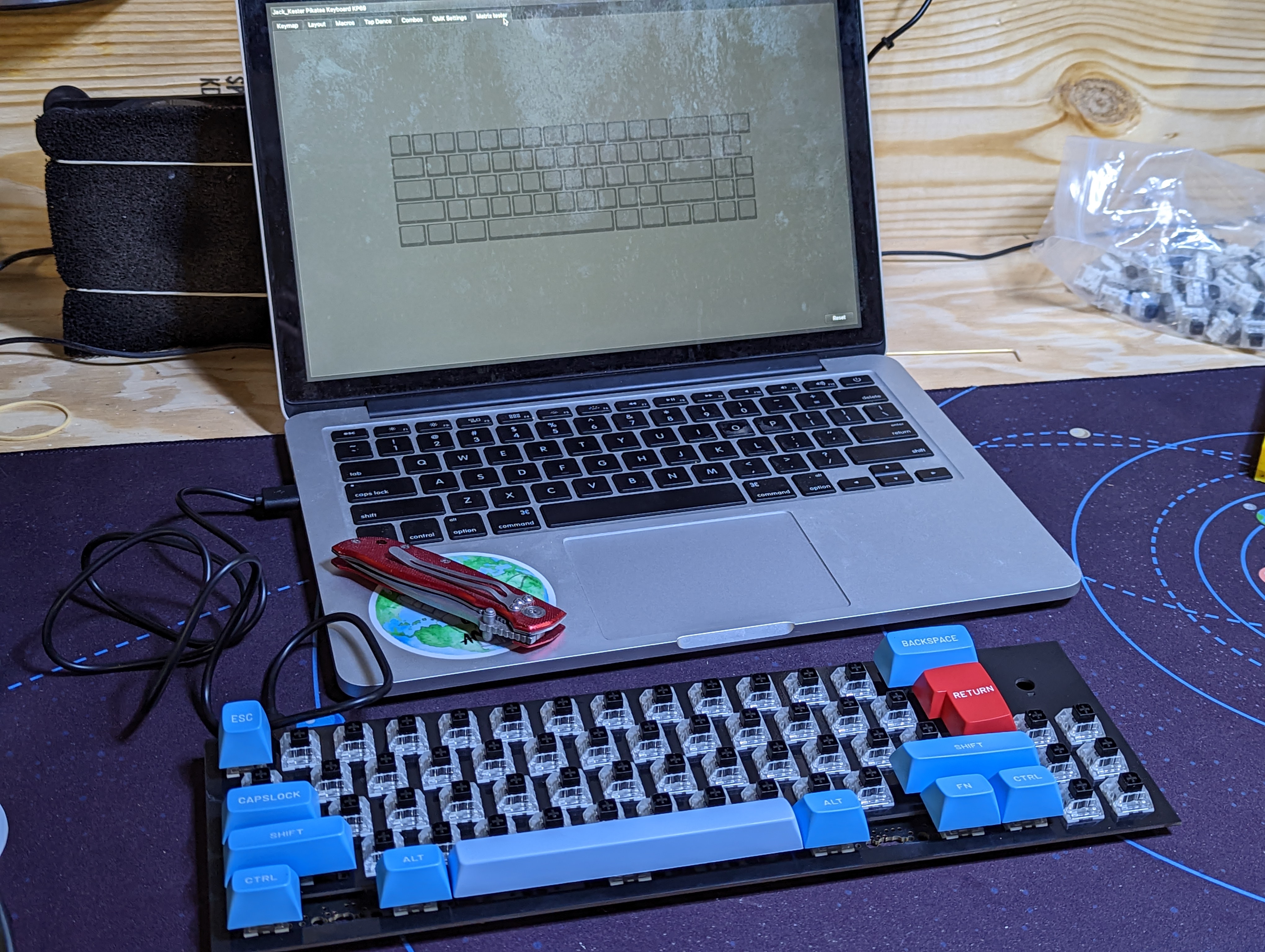
It's important to test your PCB before getting started. Download the latest version of Vial (opens new window). Plug in the PCB and go to the matrix tab. Use tweezers or flush cuts to bridge the switch connections and simulate switches. The encoder won't show up in the matrix and that is not an issue.
# Install the stabilizers
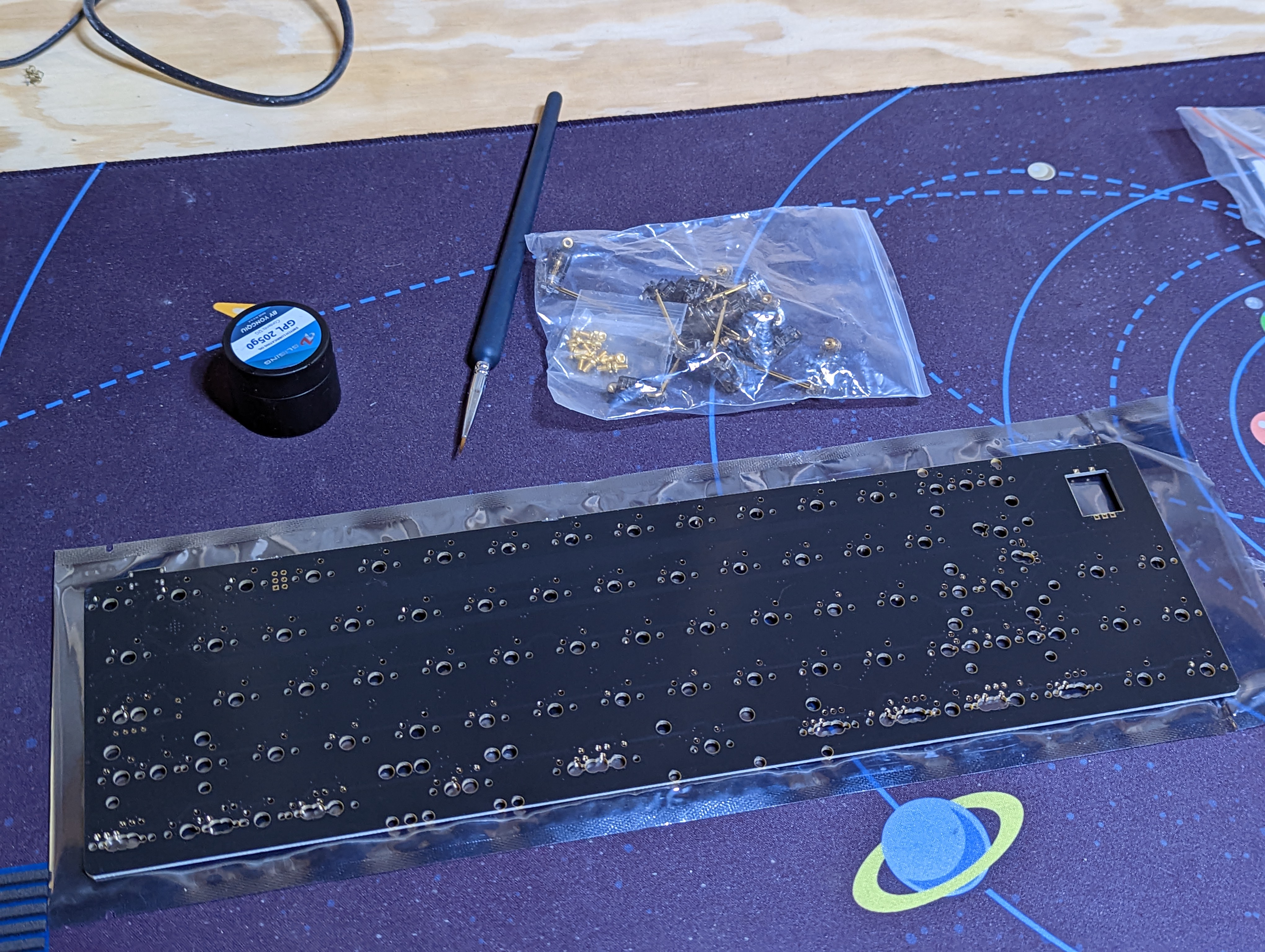
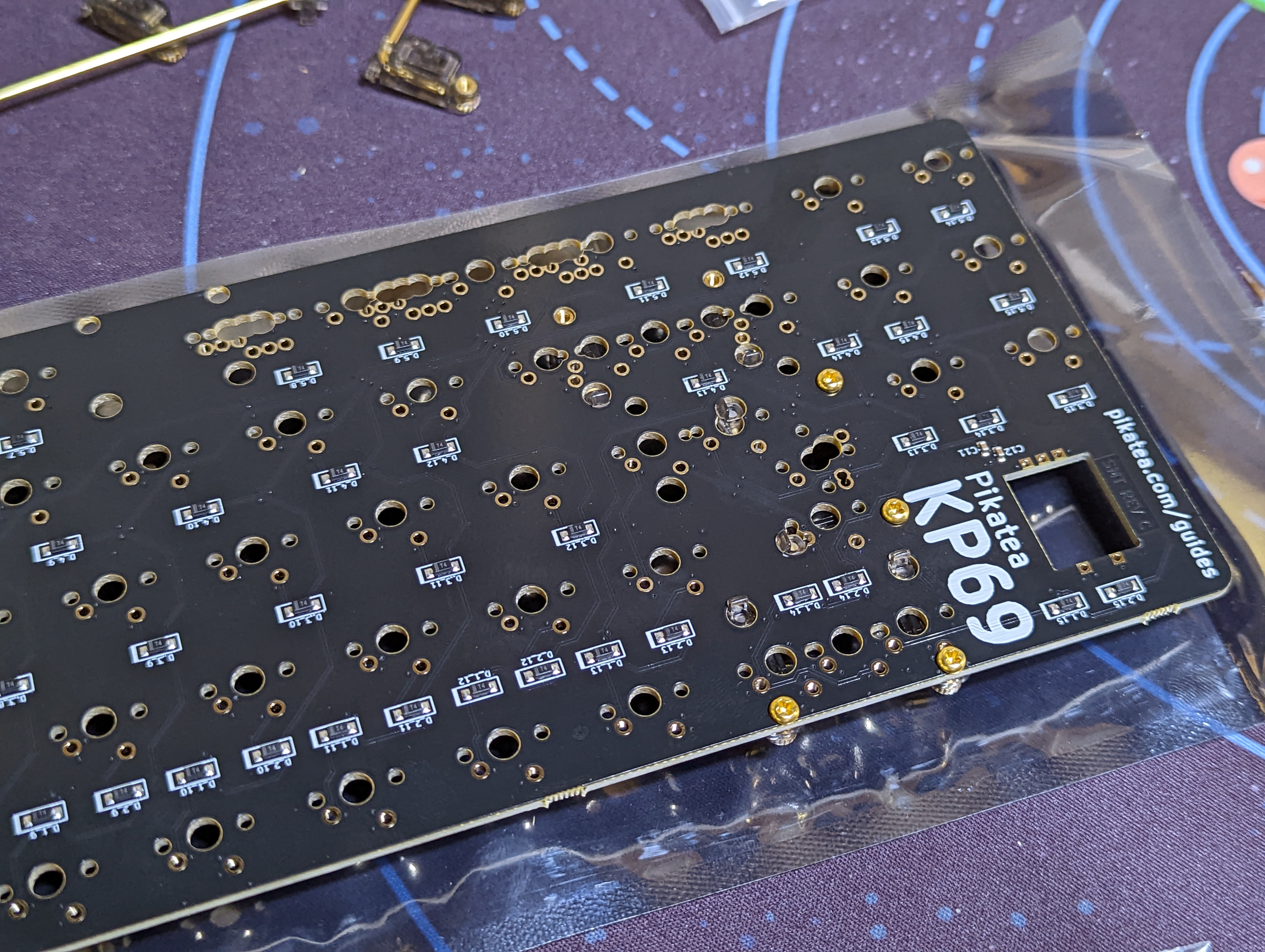
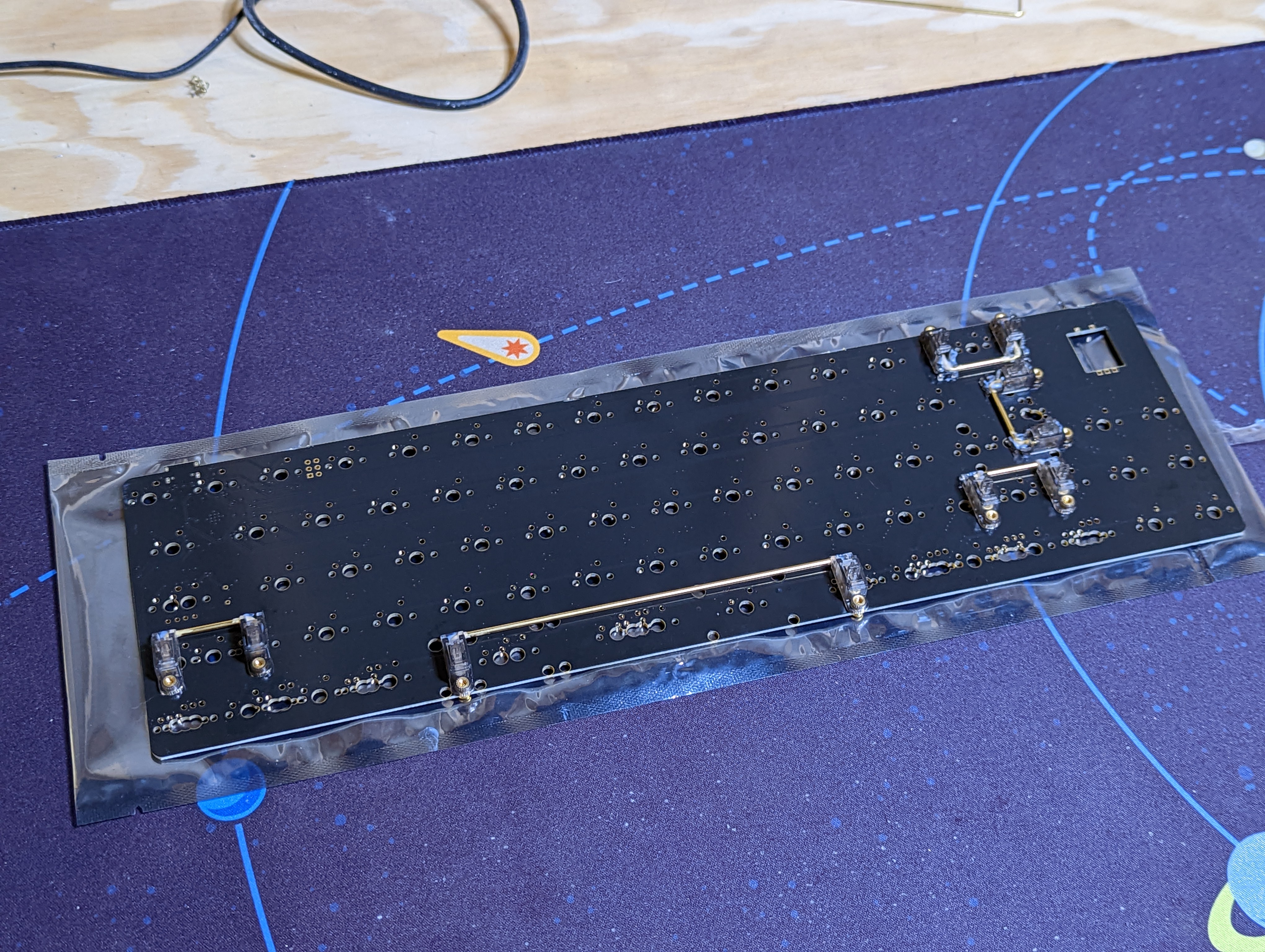
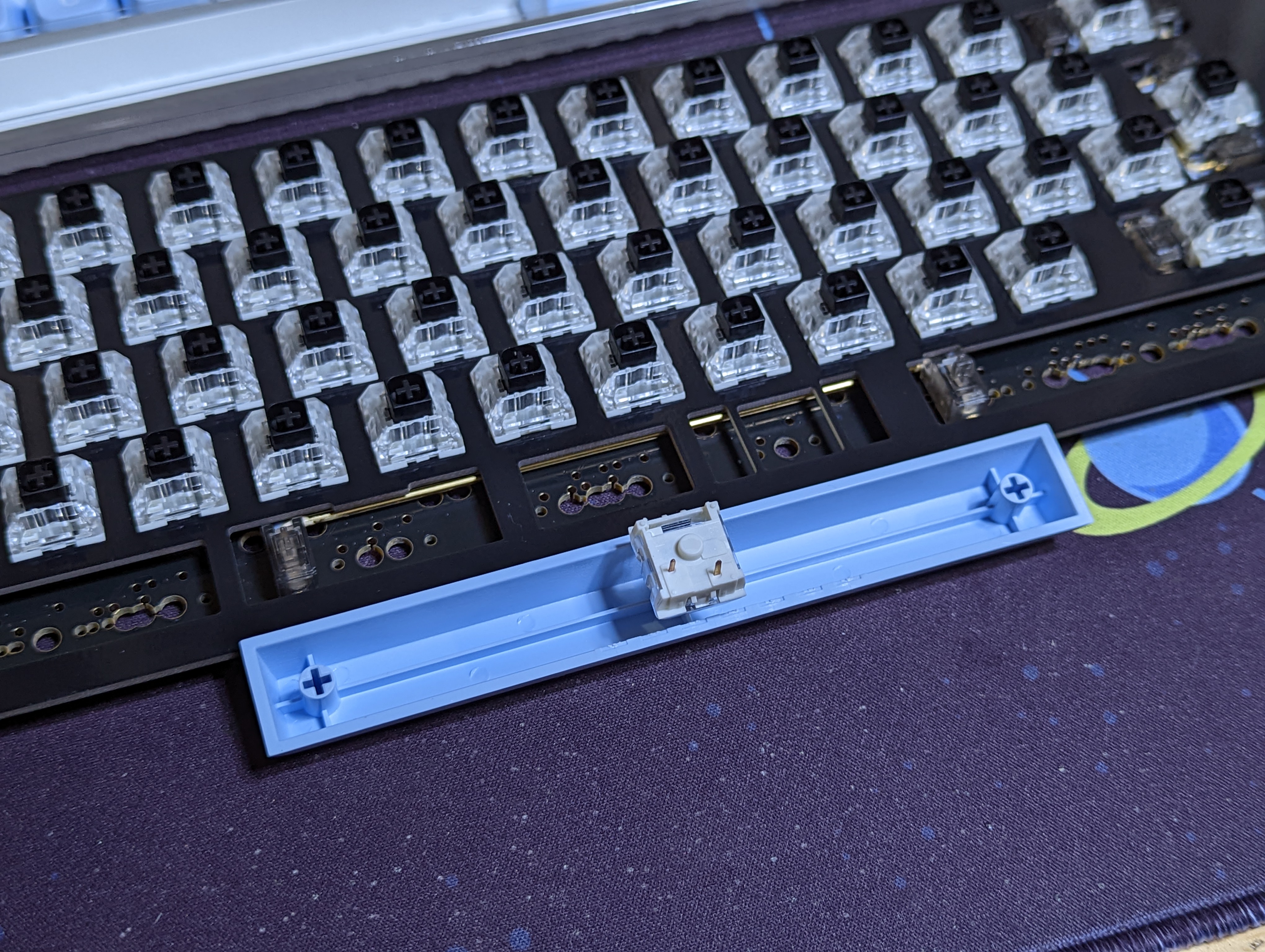
Stabilizers have to be installed before anything else. Failure to do so means de-soldering all your hard work. There are many stabilizer positions available so it's recommended to test them by installing keycaps to confirm they are in the right spot.
# Install a FEW switches
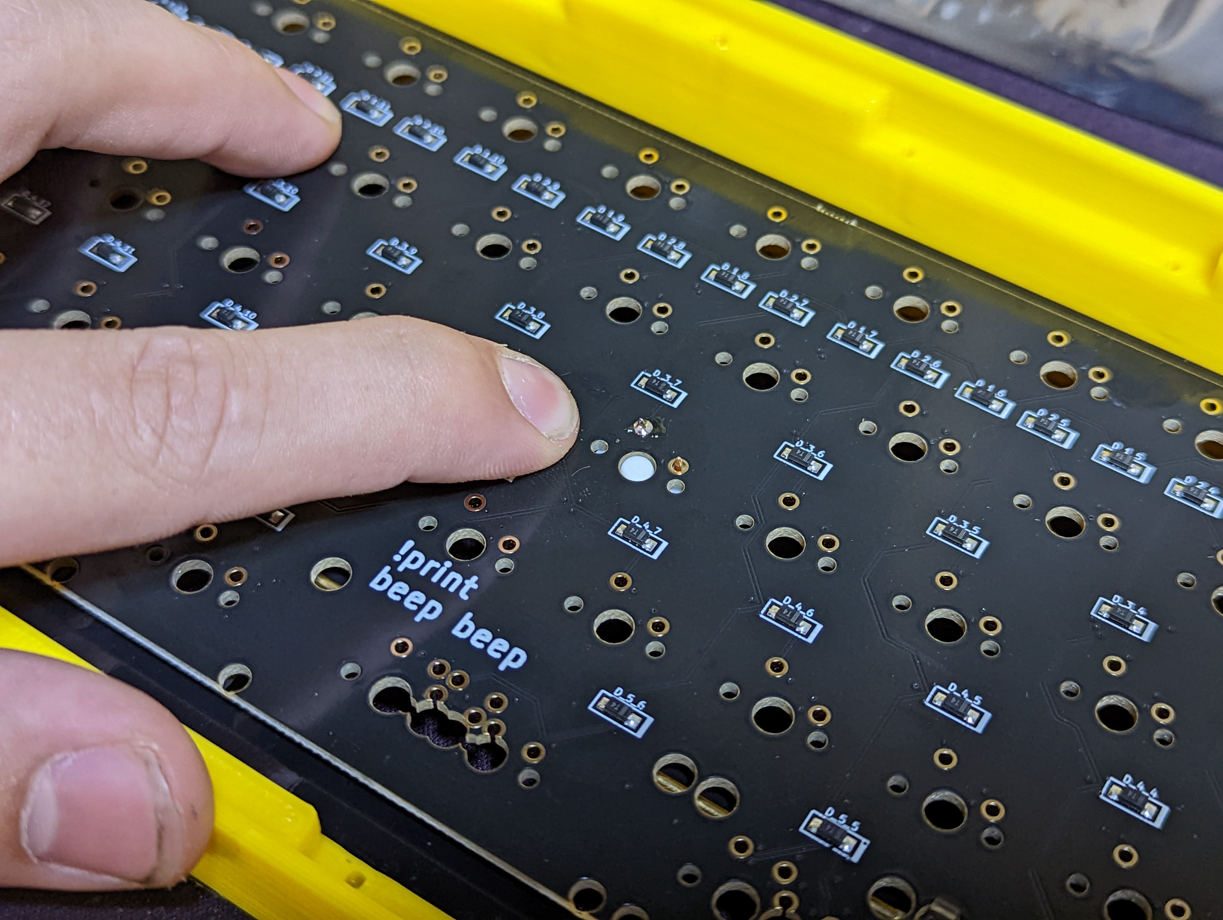
Use a couple of switches into the plate. Solder only 1 pin of each to make sure the PCB stays flush for the rest of the build and to further test that you've got the right layout. In the case of an error, you only need to de-solder a few switches and of those switches, only 1 pin.
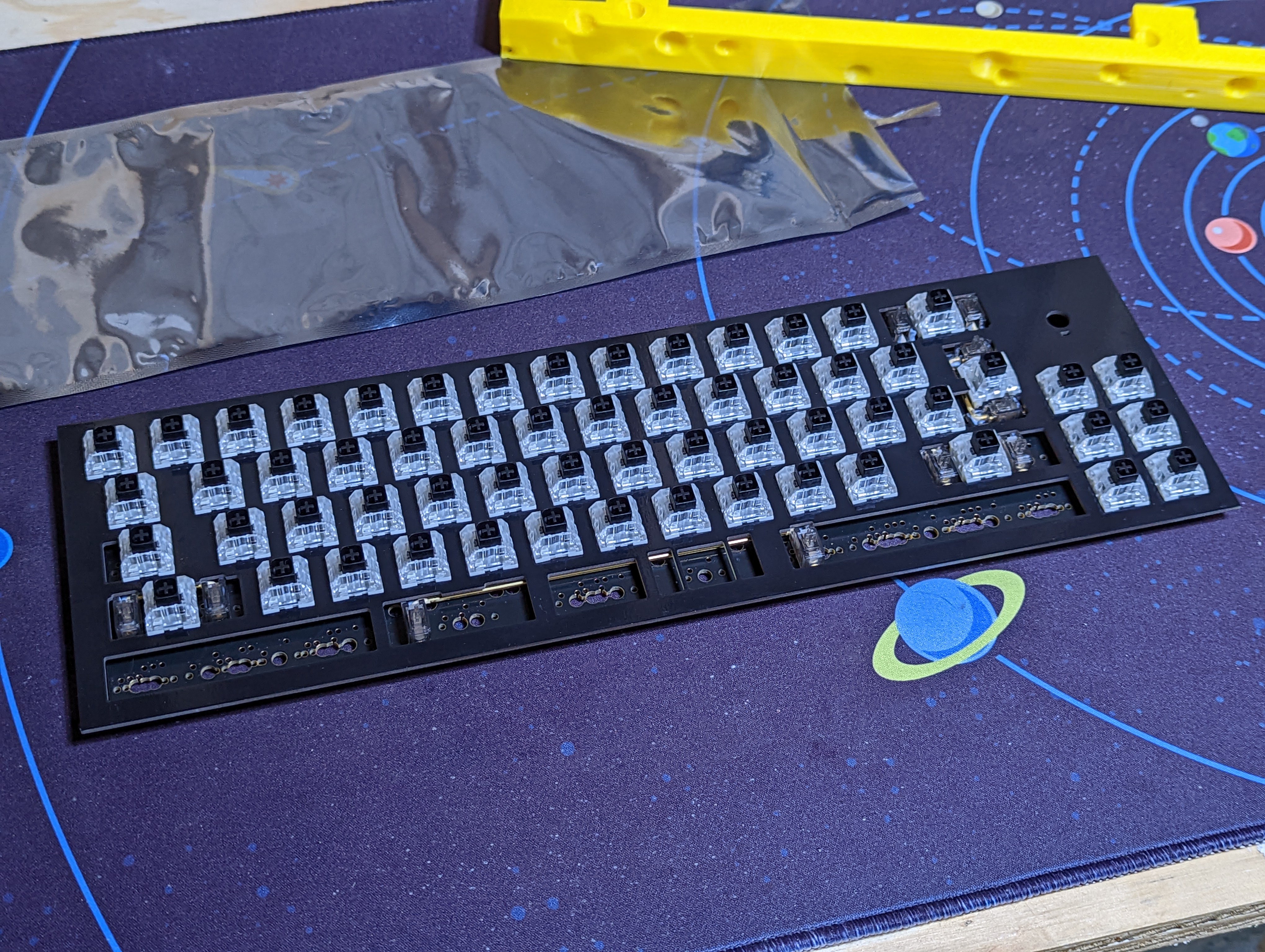
# Install some more switches. Don't solder them yet.
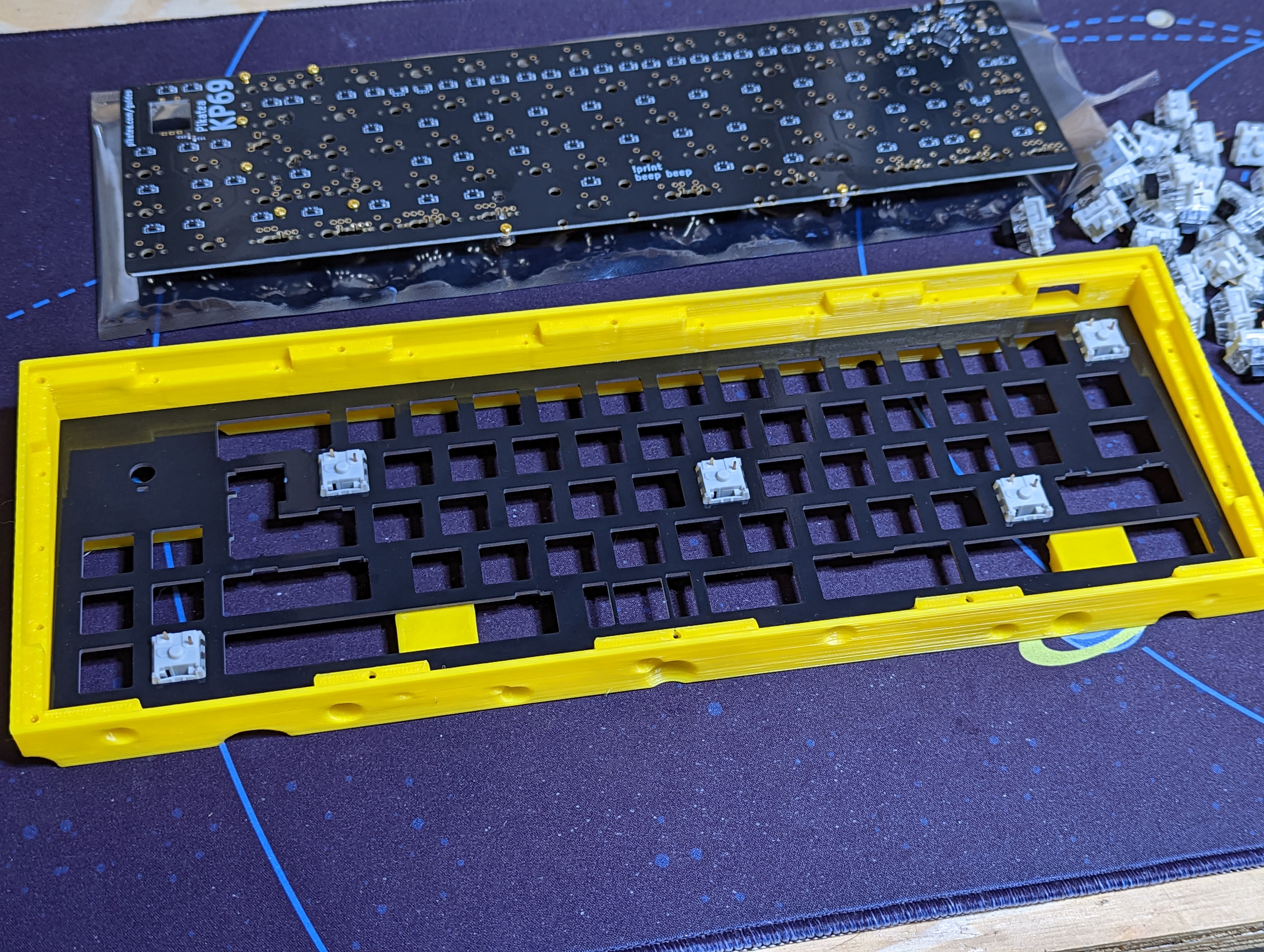
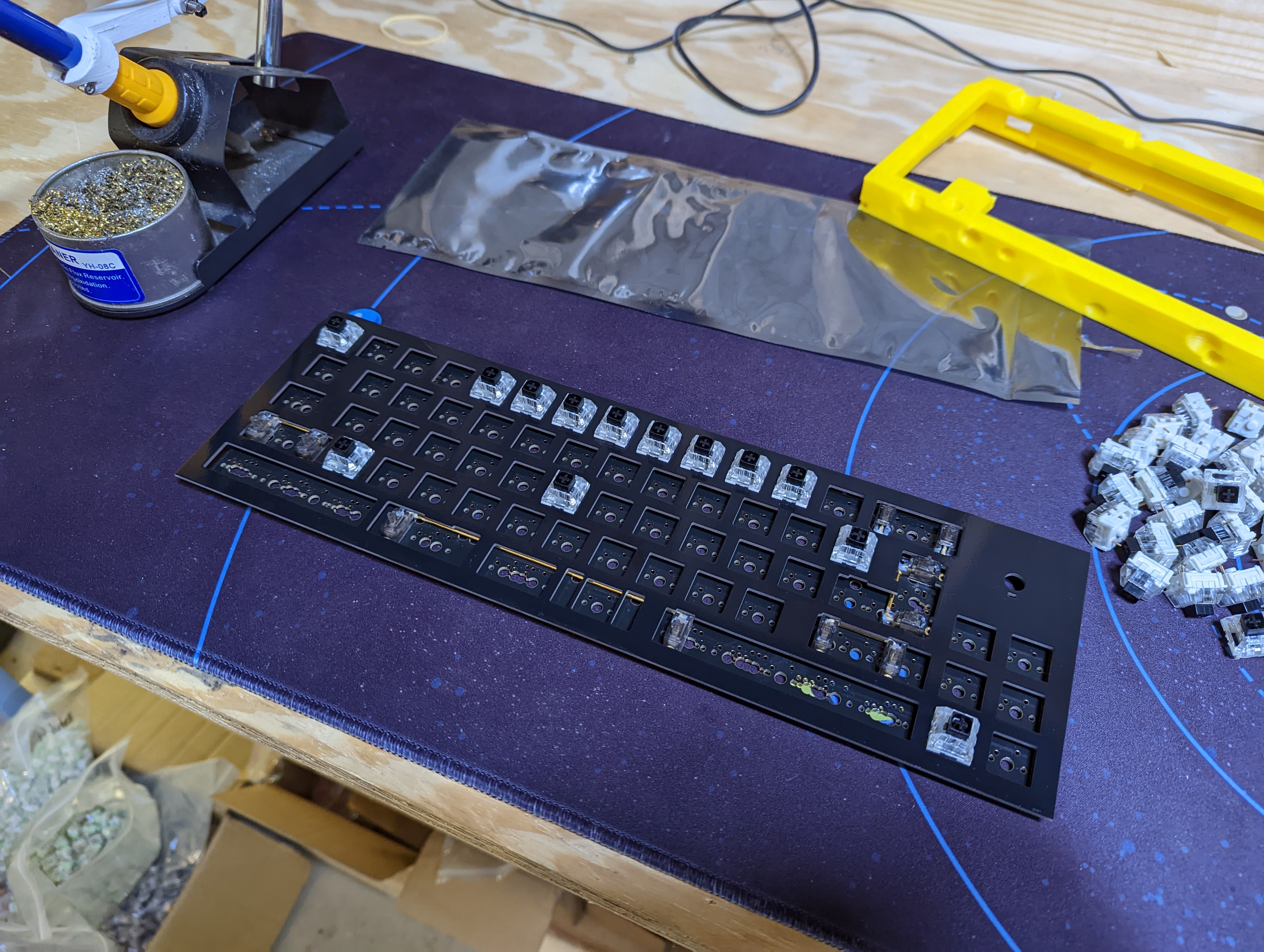
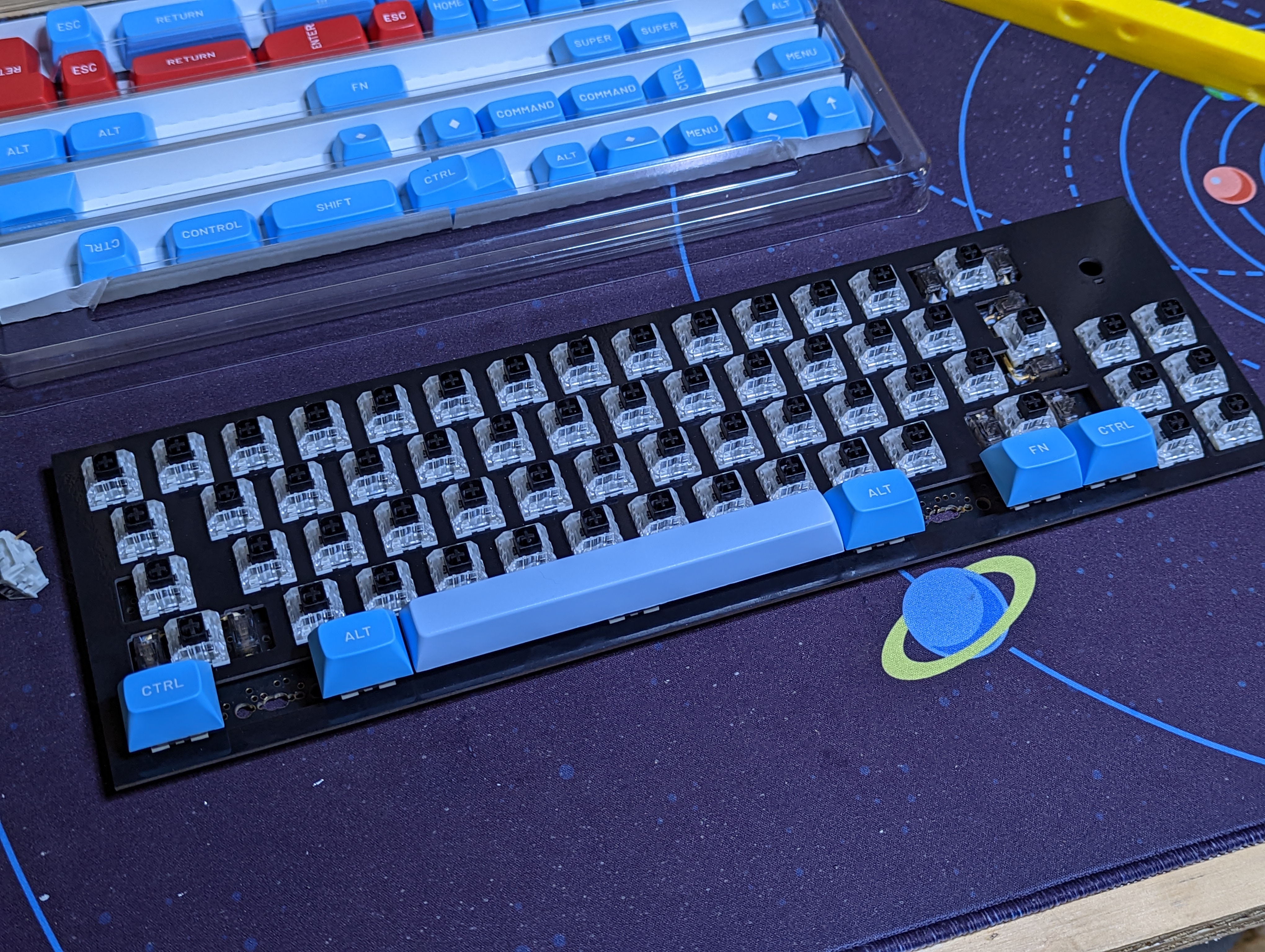
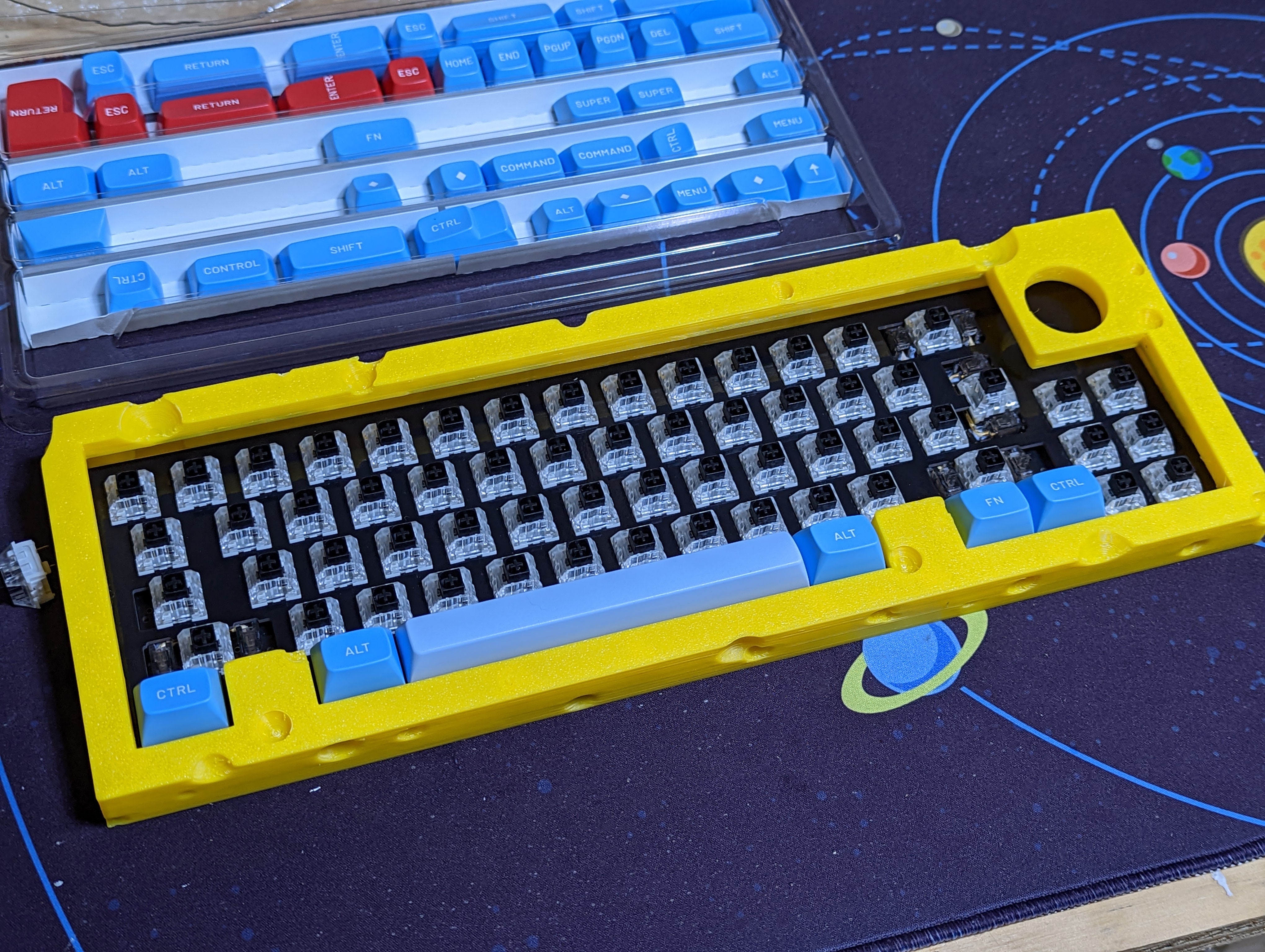
insert the remaining switches into the plate. Do not solder these yet. Install keycaps into your bottom row, and stabilizer keys. Overlay the case to confirm that all the switches are in the correct place.
# Solder the switches
After verifying the switches are in the right place and layout you want, solder them. Be sure the PCB is as close to the switch as possible while soldering.
TODO insert image of soldering
# Verify it still works
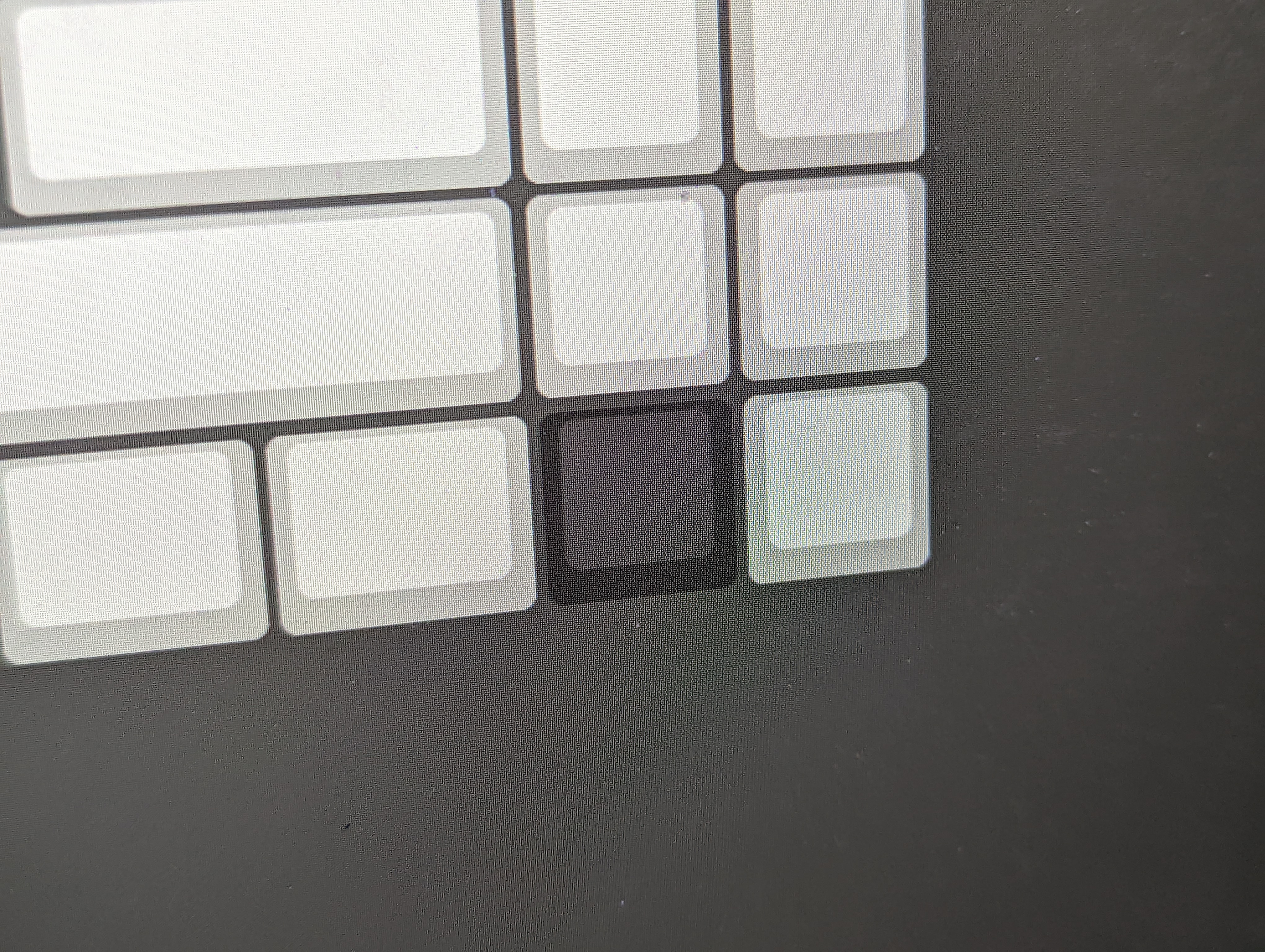
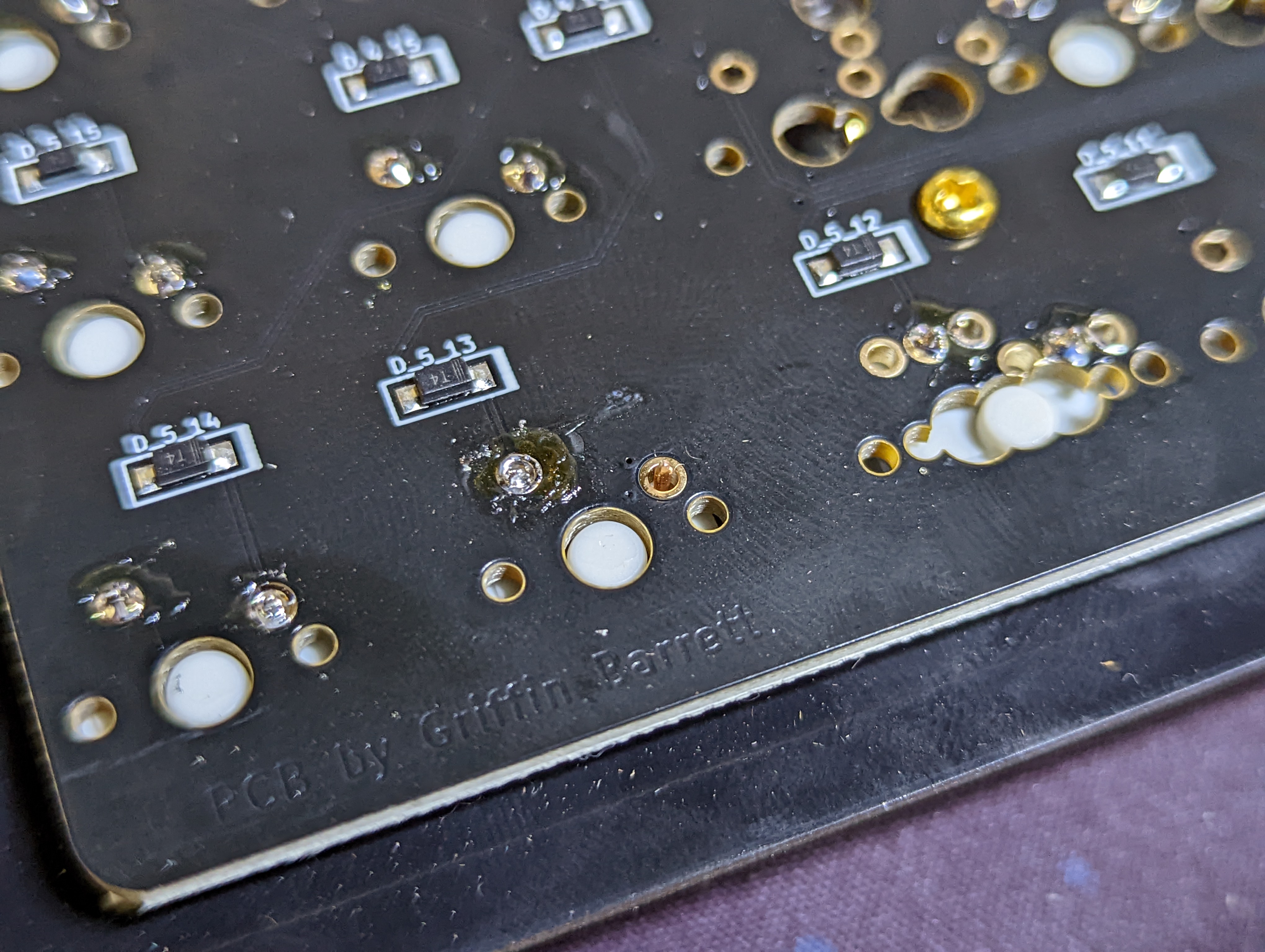
Plug the keyboard back into the keyboard and reopen Vial. Go to the layout tab and select the layout options that match your keyboard. Go to the matrix tab and test each button. As you can see, I missed a switch!
oops I missed a switch!
# Install the Rotary Encoder
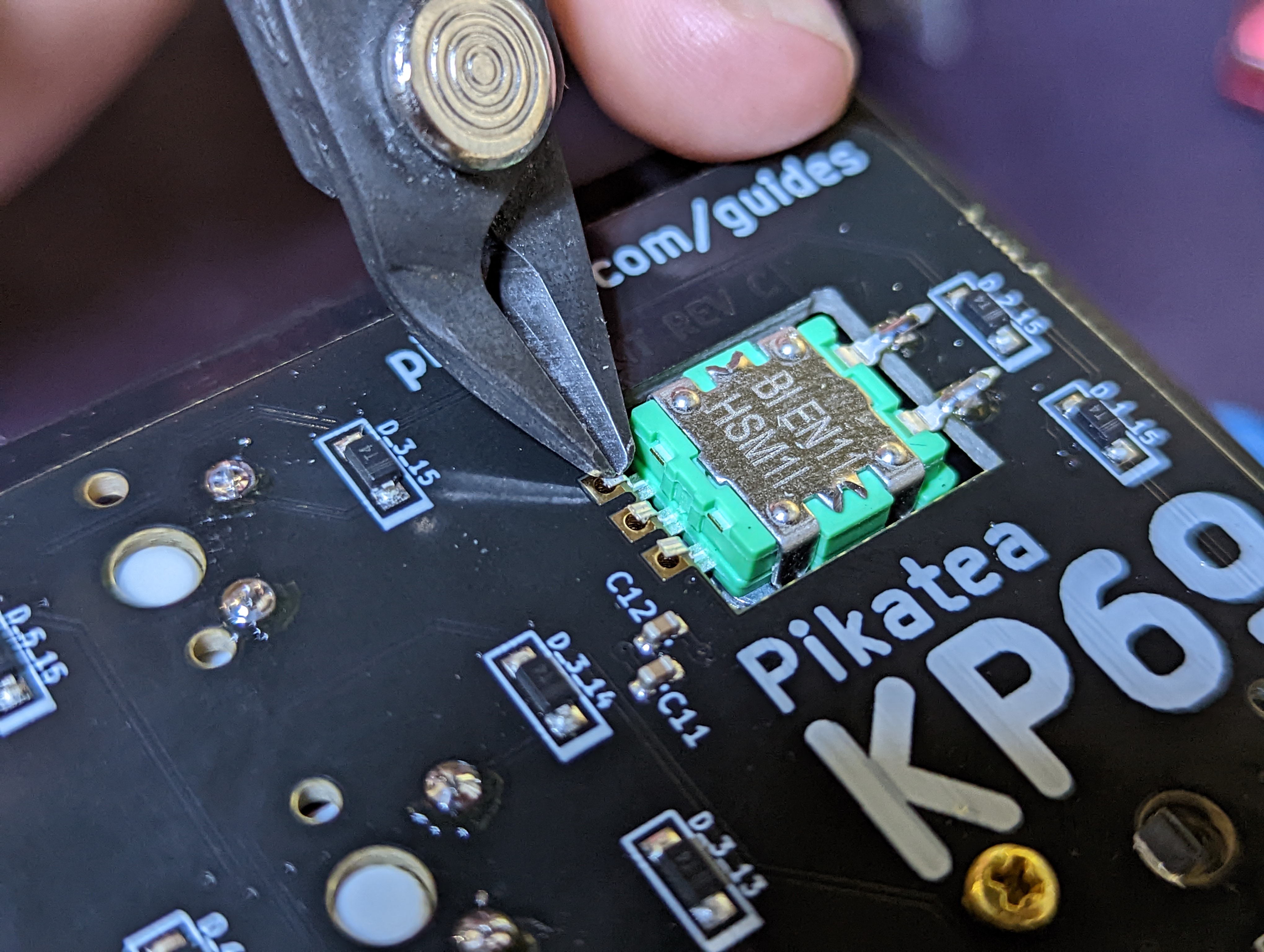
Next up is the rotary encoder. (Note: the encoder may already be prepped but here are the directions in case yours is not). Prep the rotary encoder by snipping the mounting tabs with snips or wire cutters. Cut the set of 3 pins shorter so they are flush with the bottom of the rotary encoder. Lastly, bend the set of 2 pins so they are pointing straight out with a slight angle.
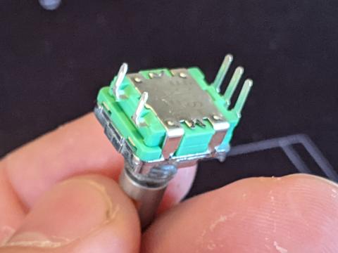
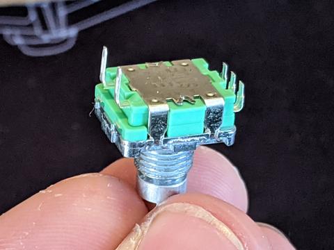
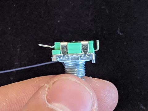
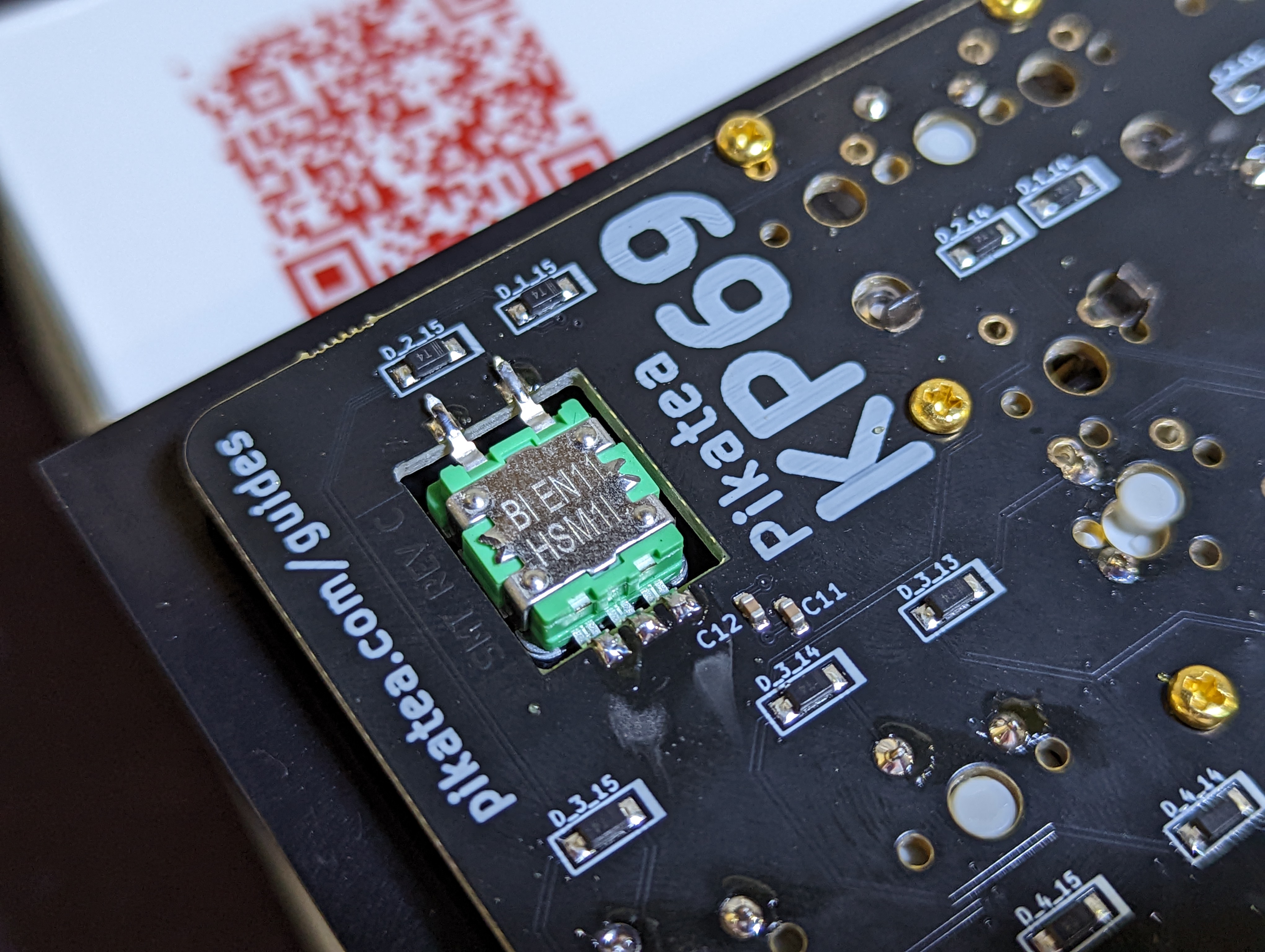
Place the rotary encoder in the hole of the top plate and hand tighten the washer and nut to hold it in place for soldering. Don't tighten this with any tools just yet. Use the pictures shown to ensure the correct orientation.
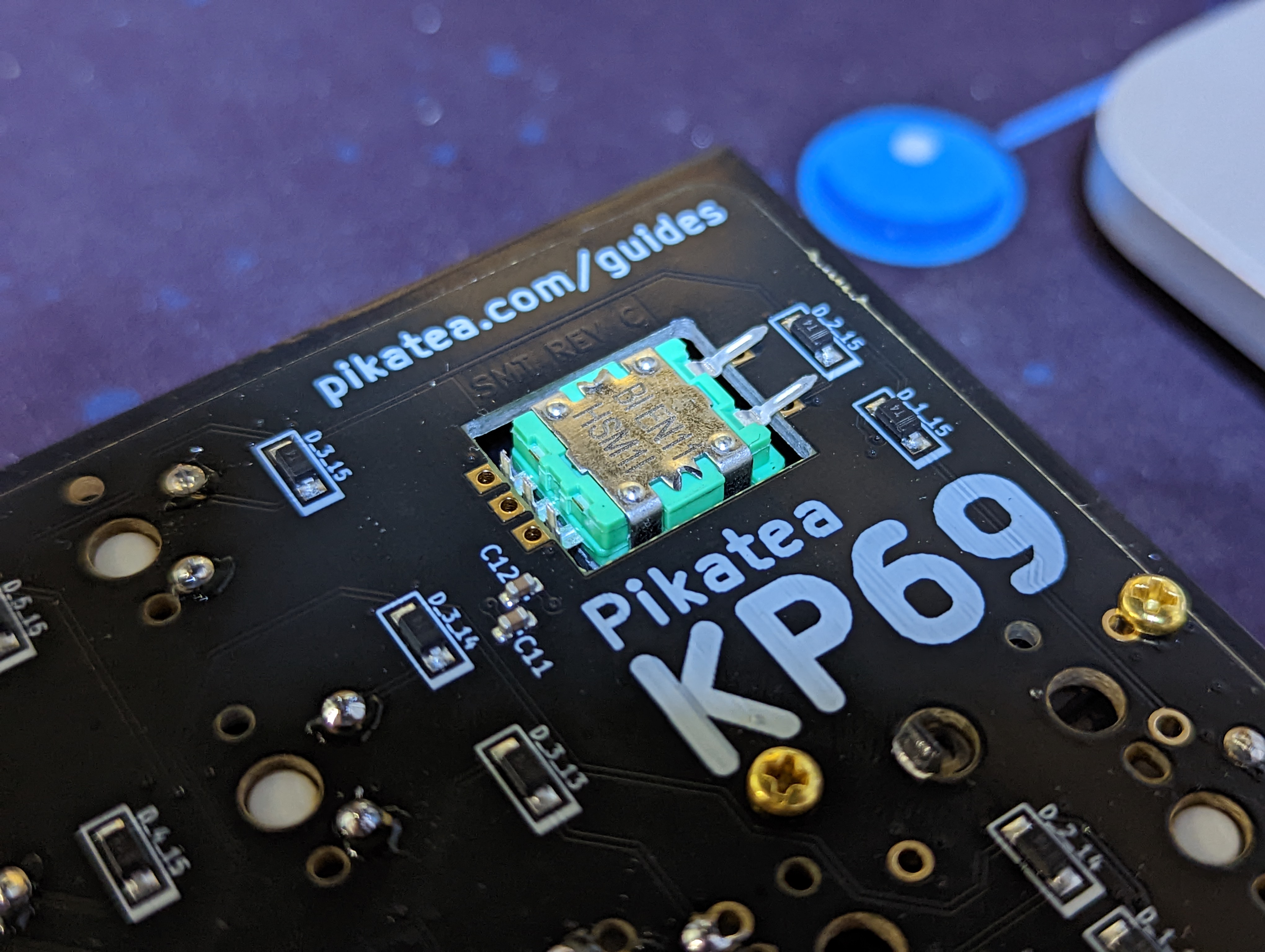
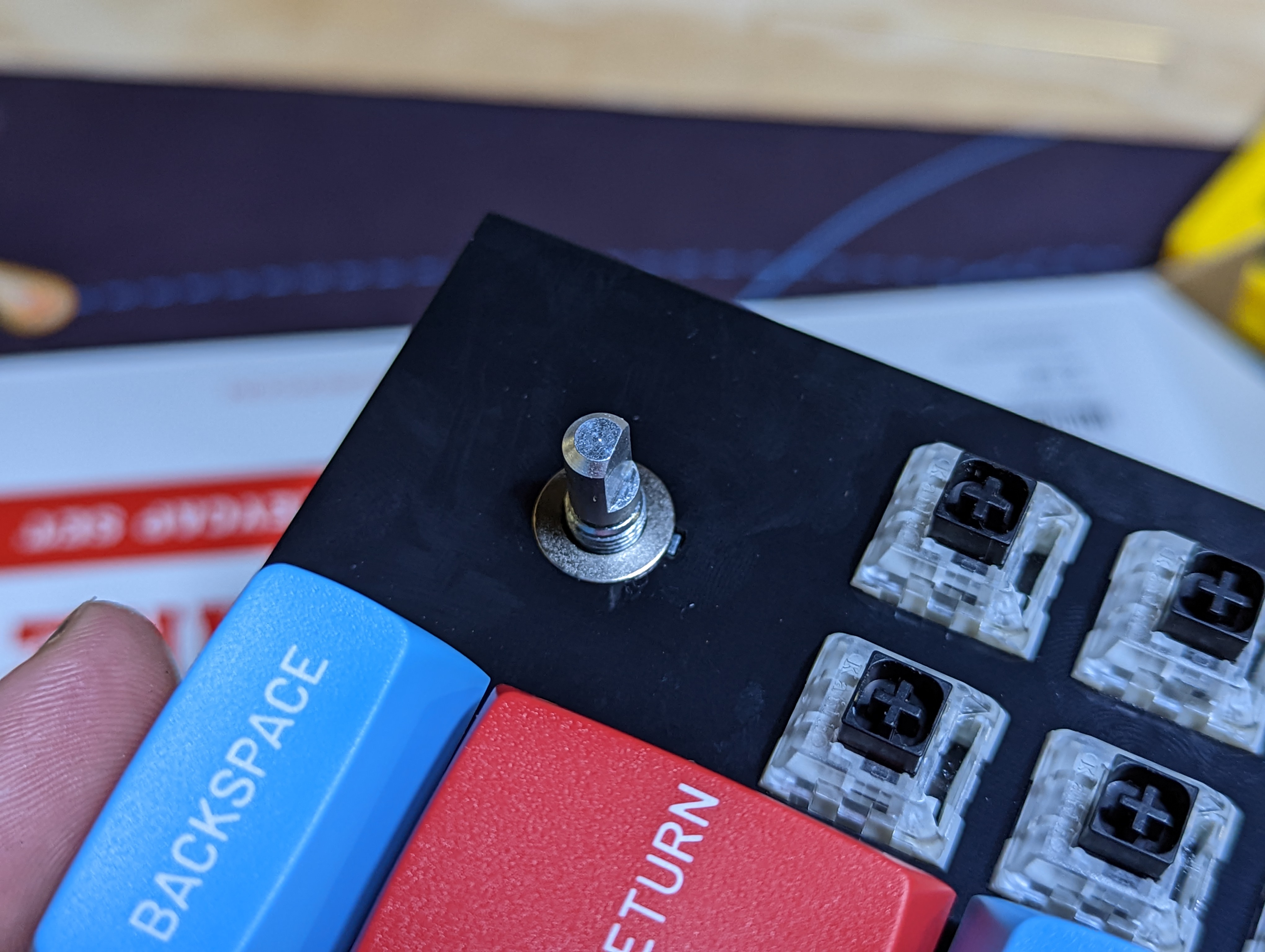
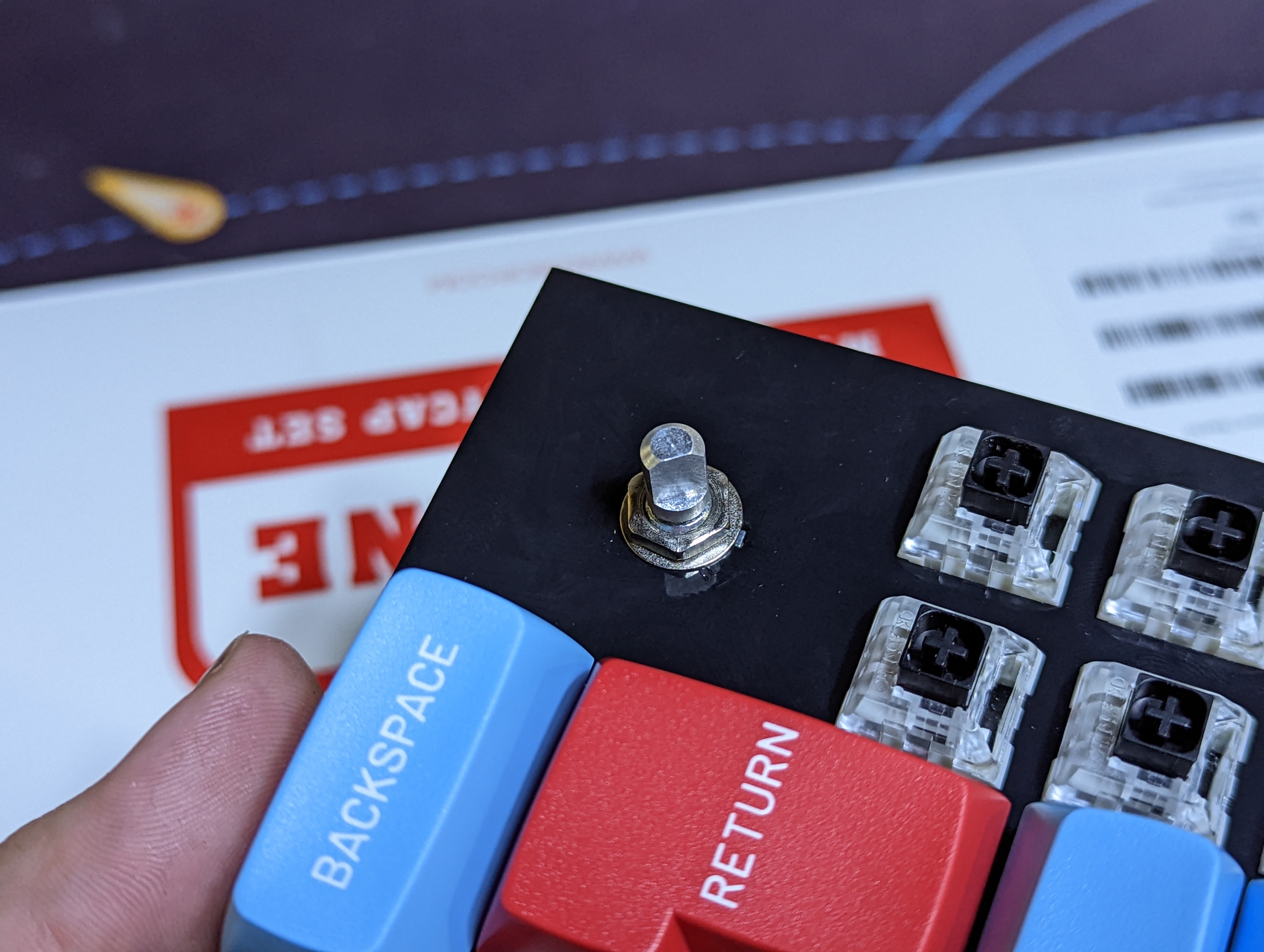
You may have to straighten the encoder after hand tightening it.
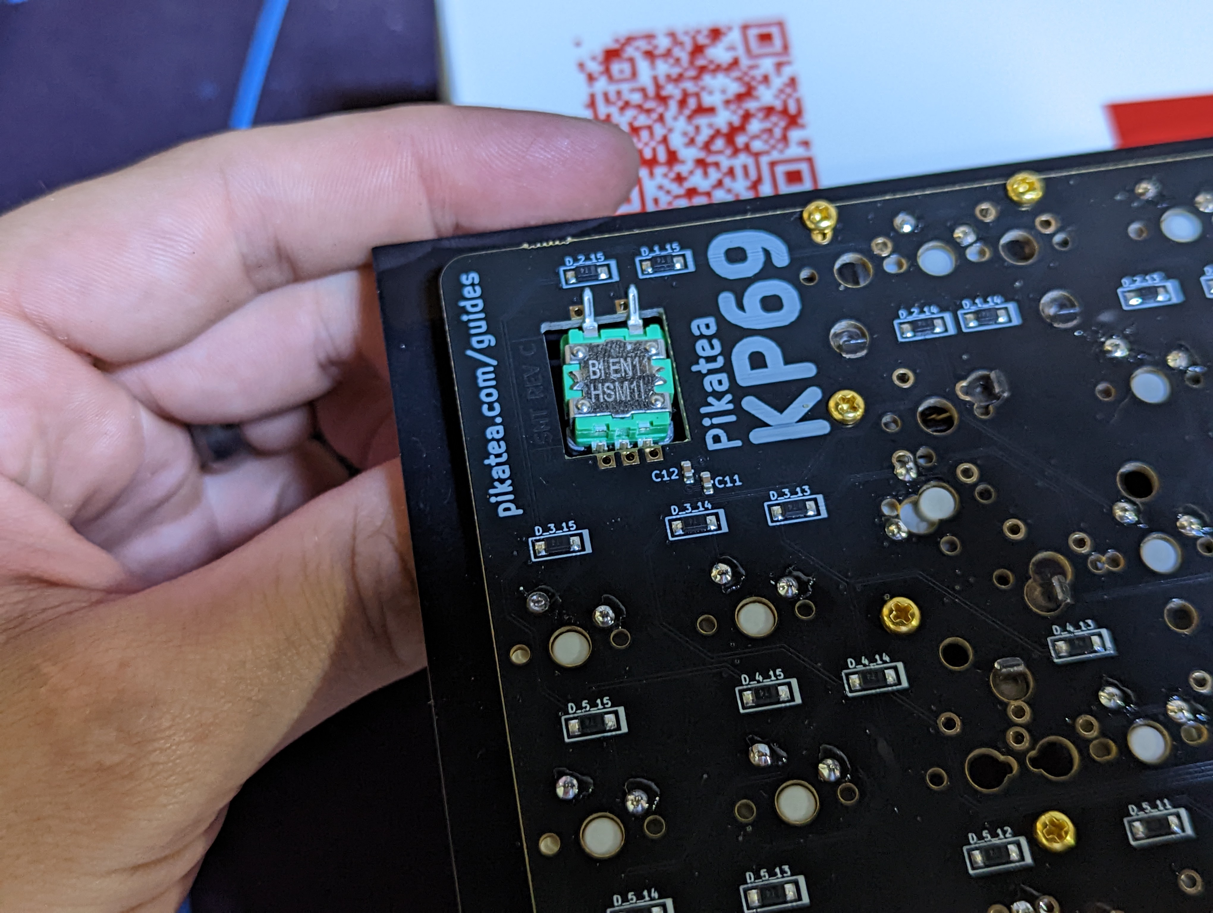
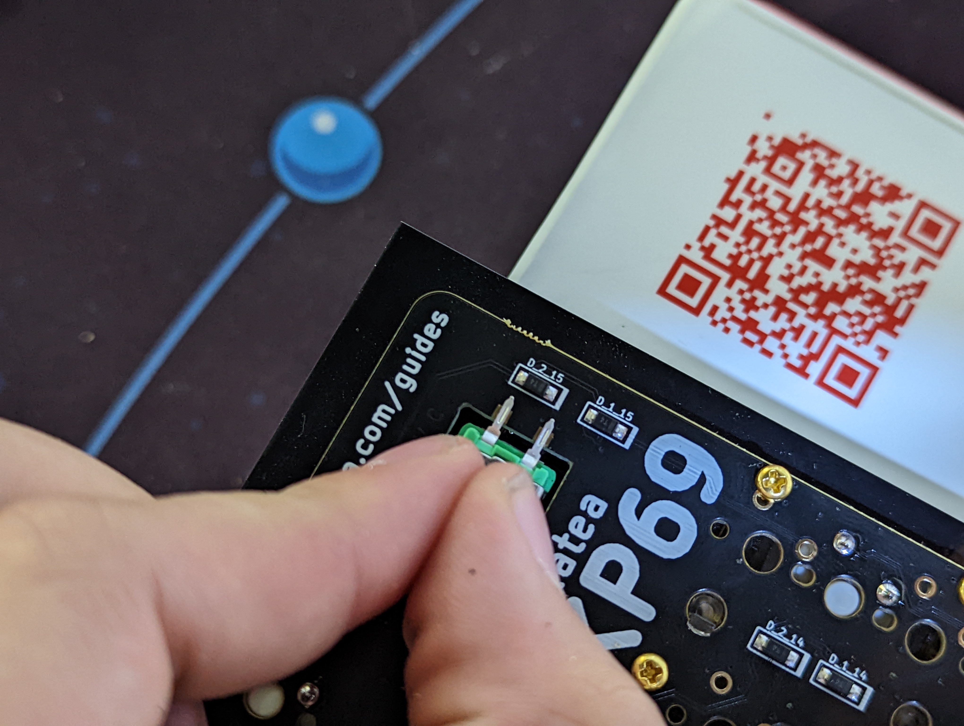
# Solder the Rotary Encoder
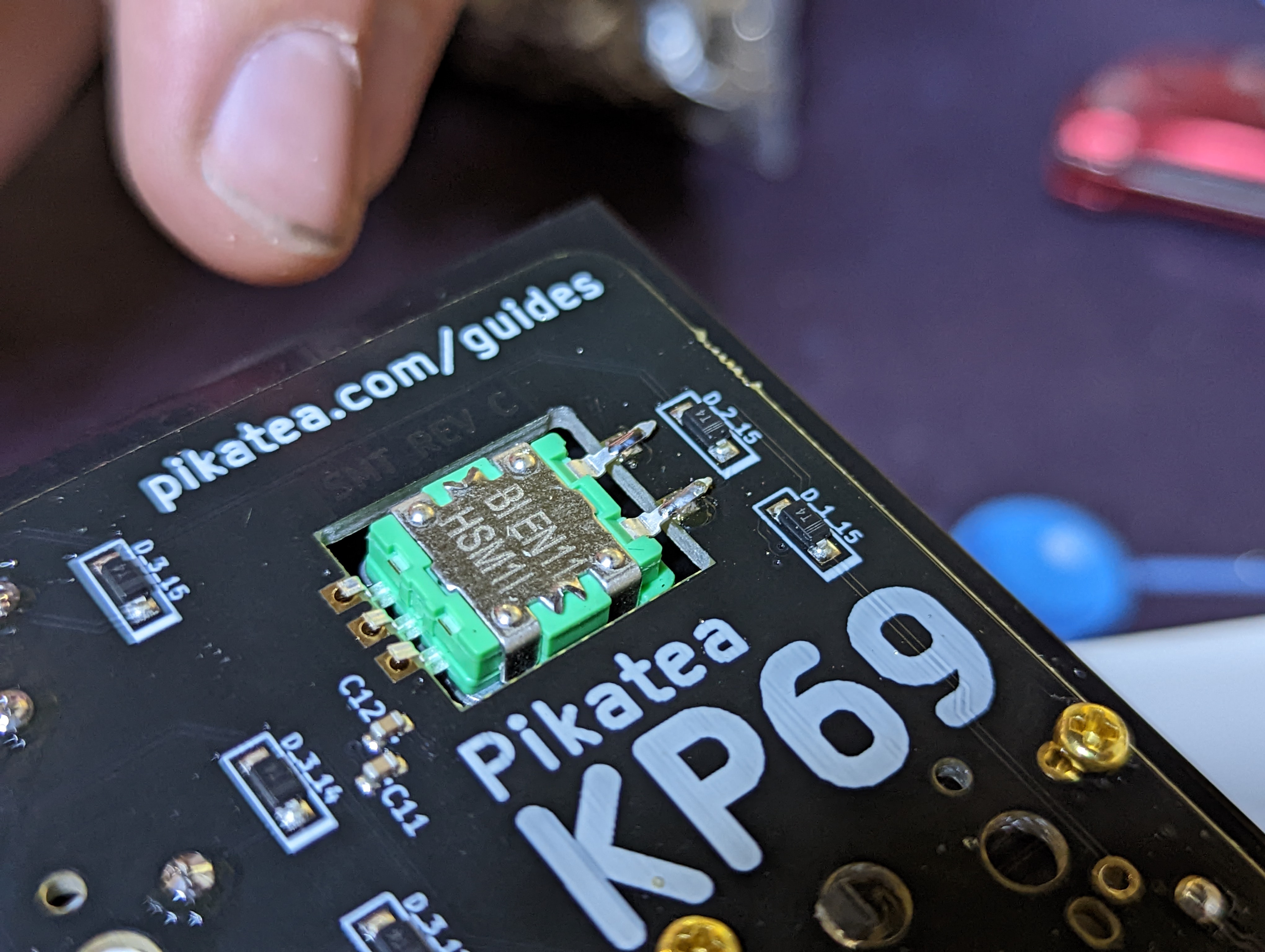
After the rotary encoder is in place, it is time to solder it. The 2 bent pins on the rotary encoder are resting just above the pads were they need to be soldered to. The 3 shorter pins on the rotary encoder are placed just to the side of the pads were they need to be soldered to. They do not go through the small holes. Take a look at the picture shown for a better explanation. It may help to bend the set of 3 pins a little towards the PCB.
# Tighten the Rotary Encoder and install the knob
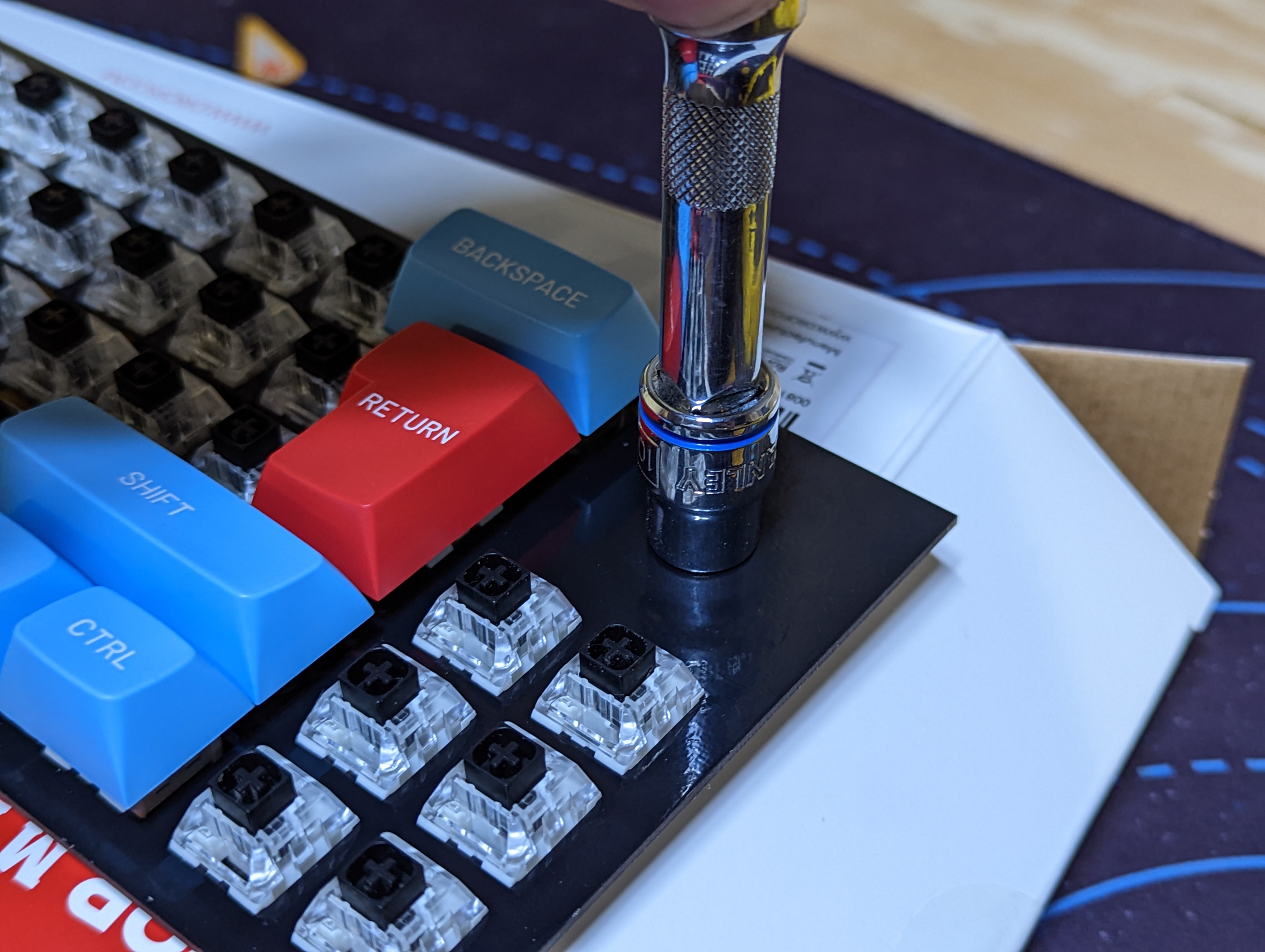
Use the 10mm socket to fully hand tighten the encoder. It's recommended to install the knob now. It can be difficult to install the knob after the case has been installed.
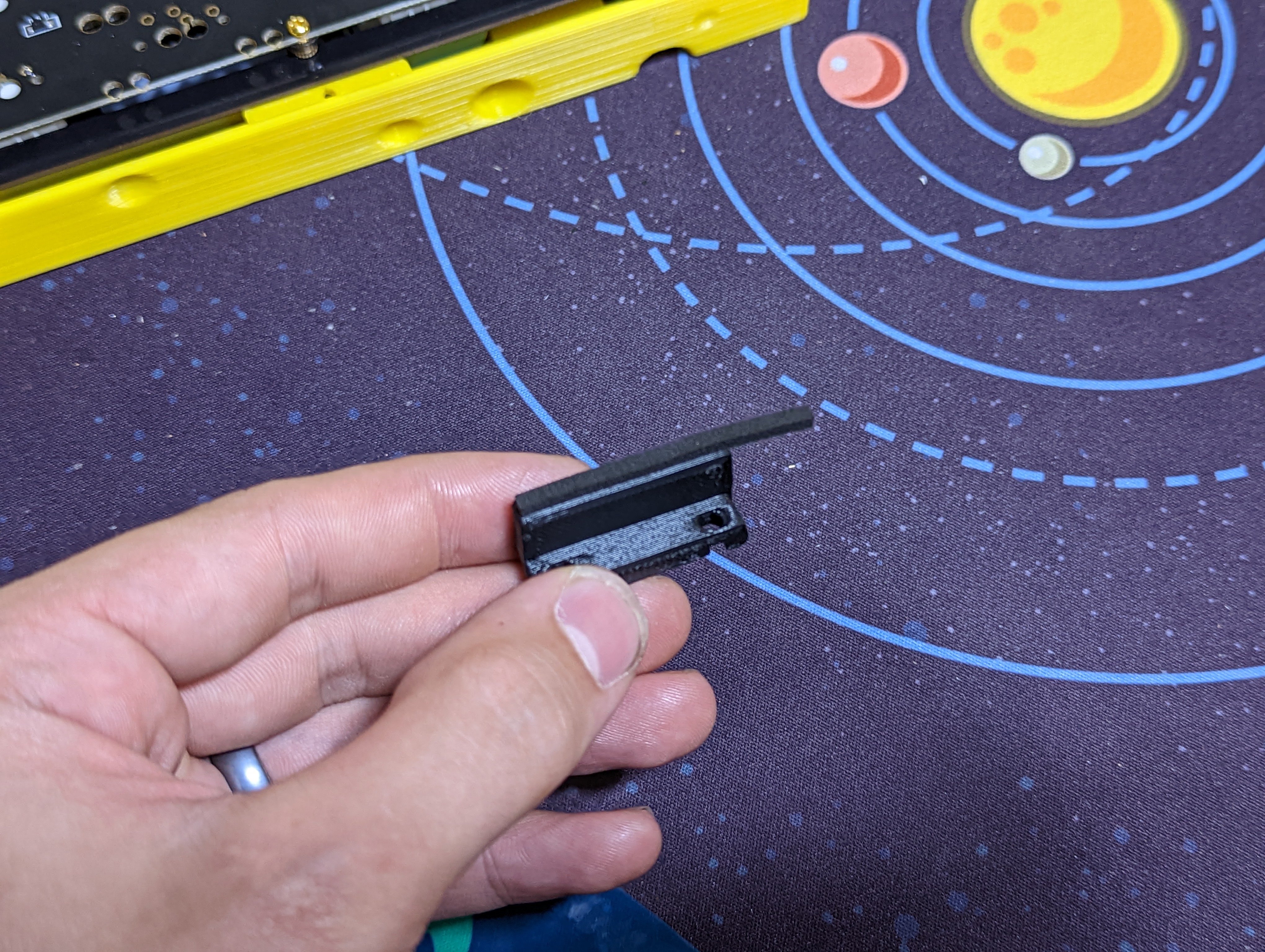
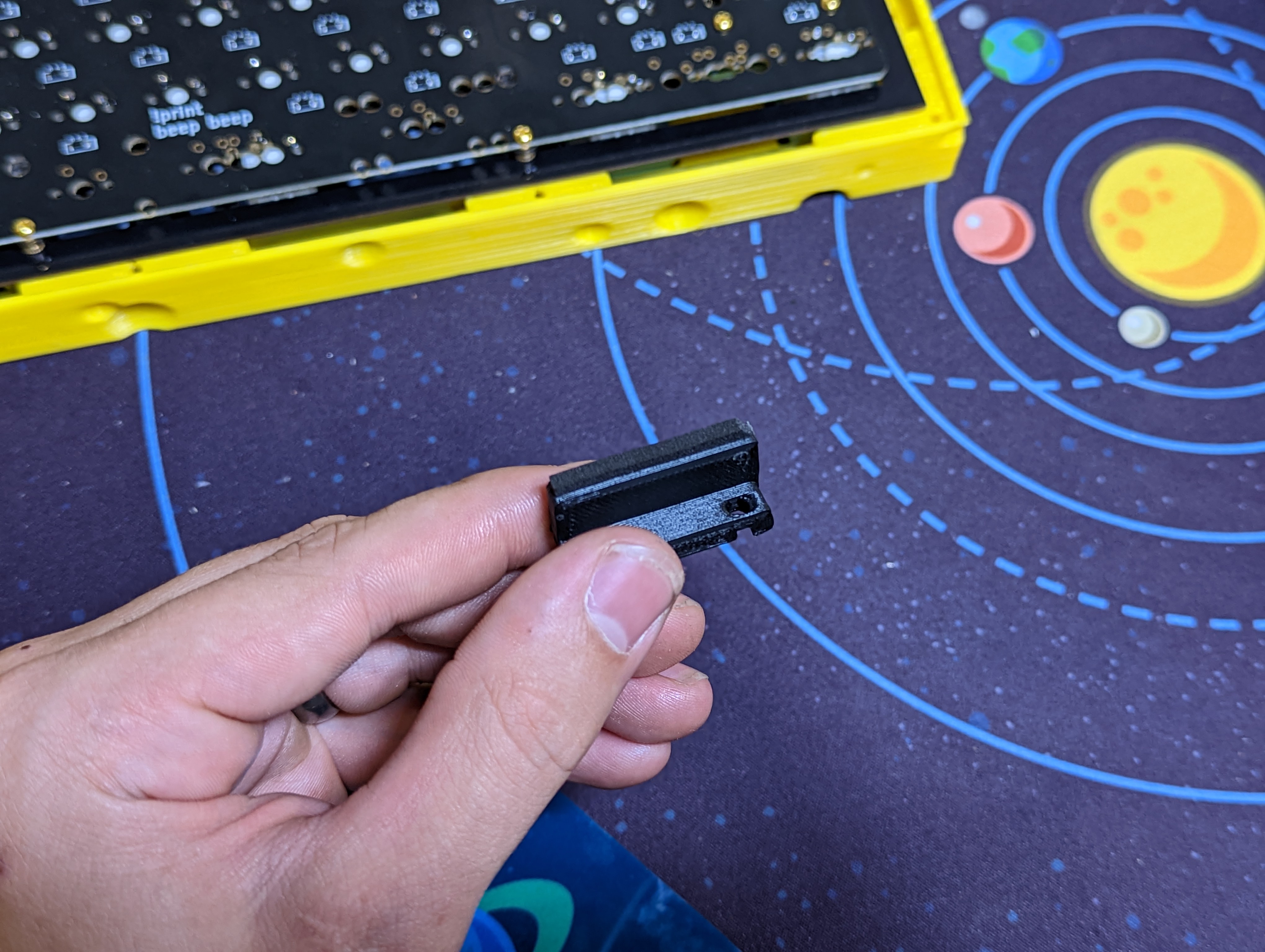
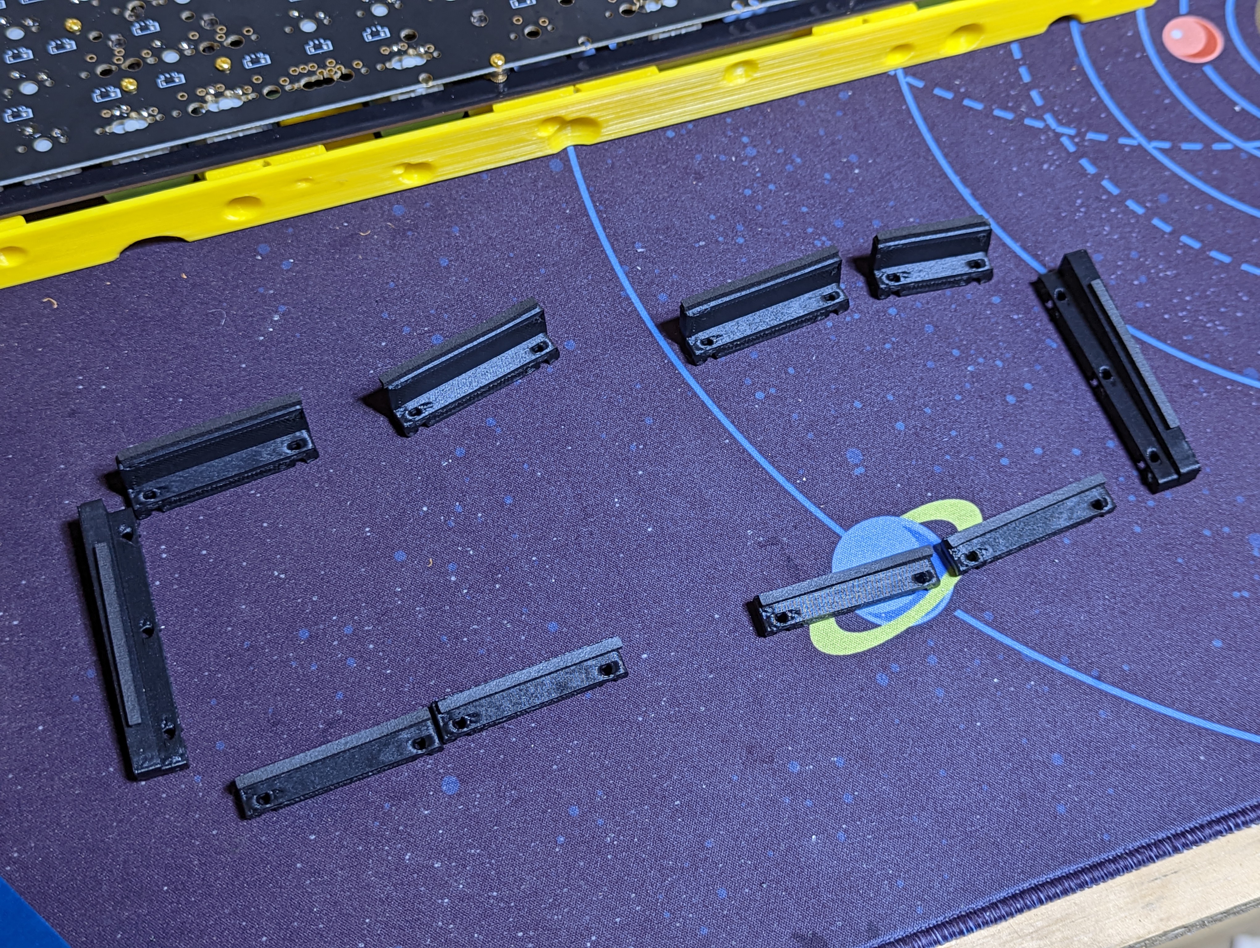
# Add Gaskets to the brackets
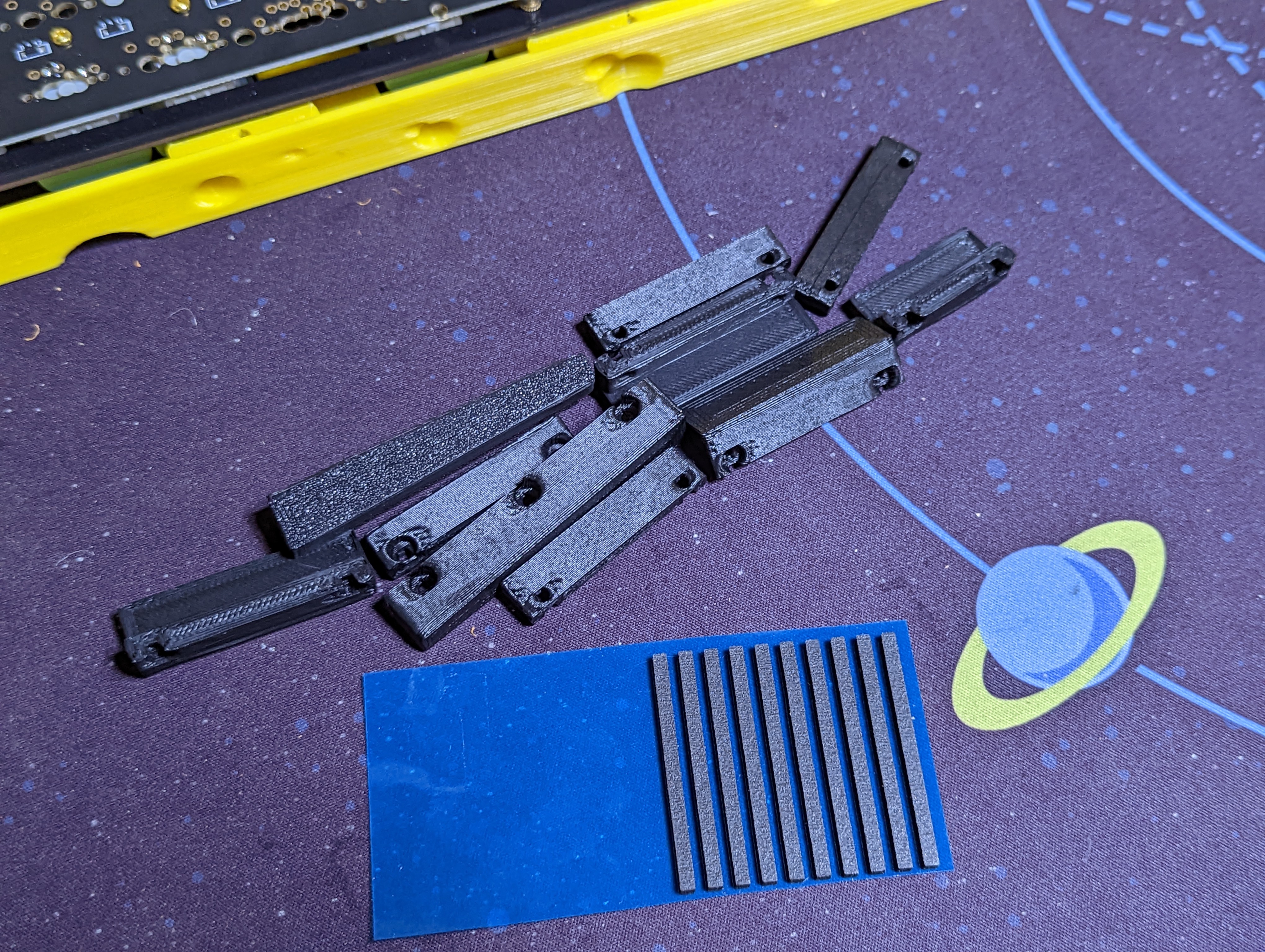
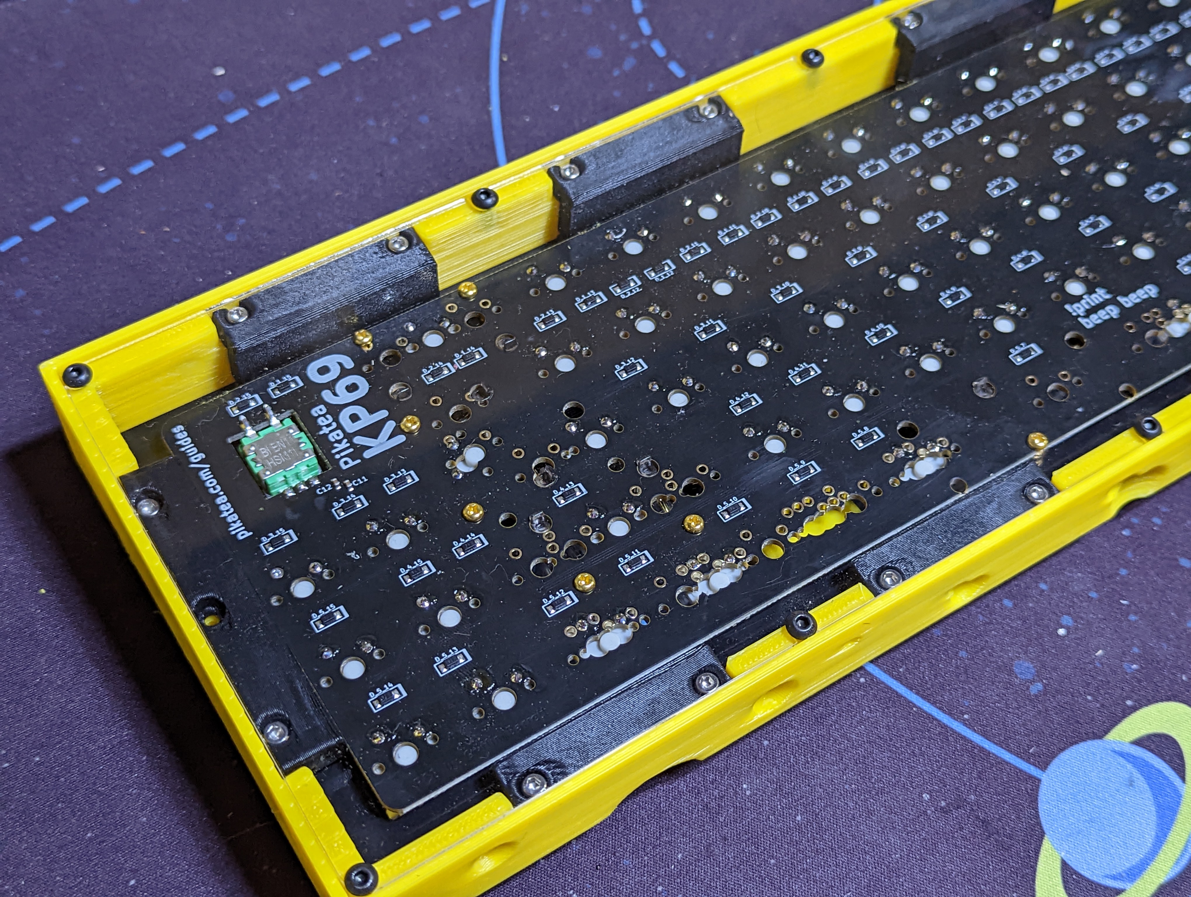
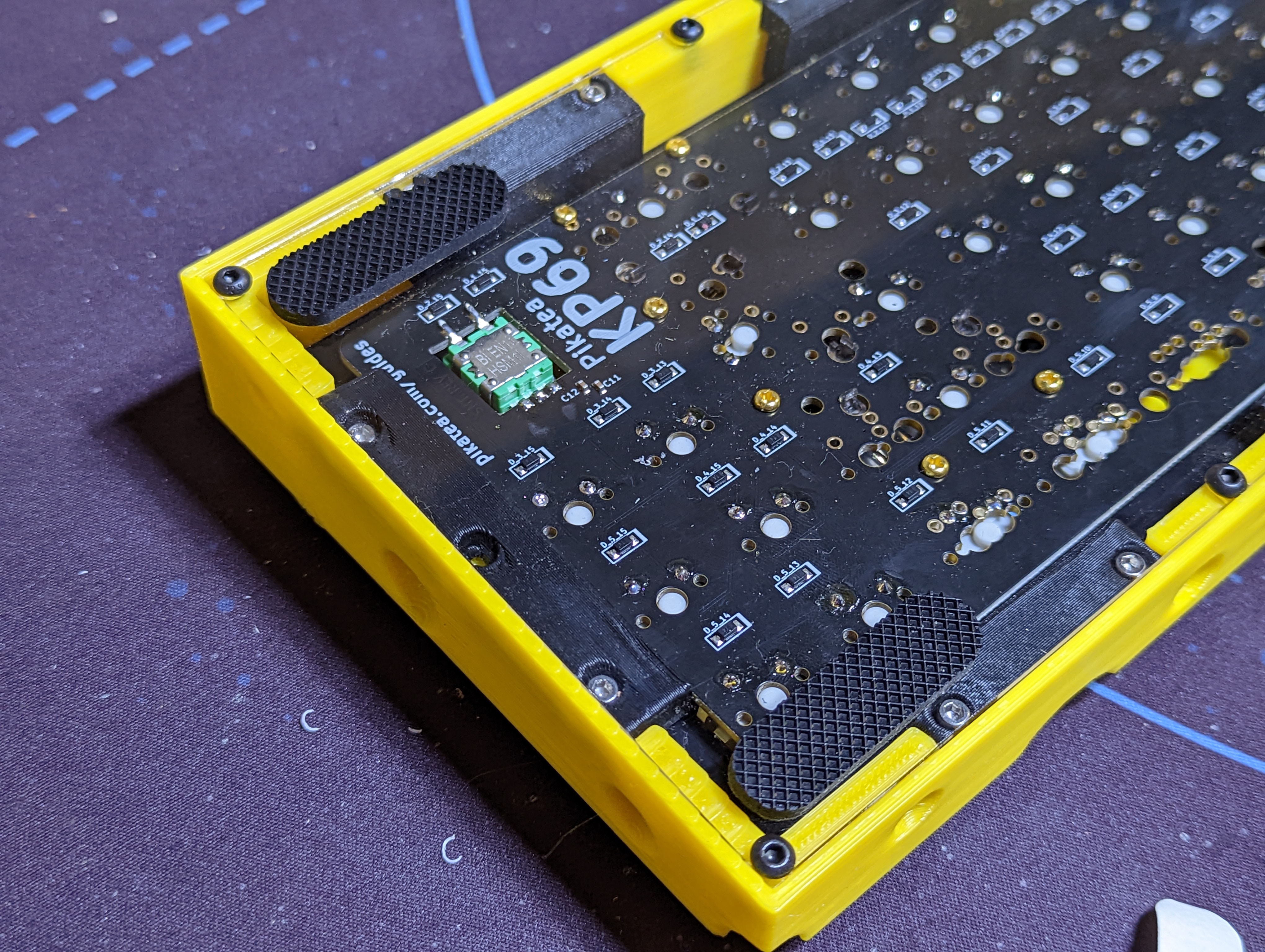
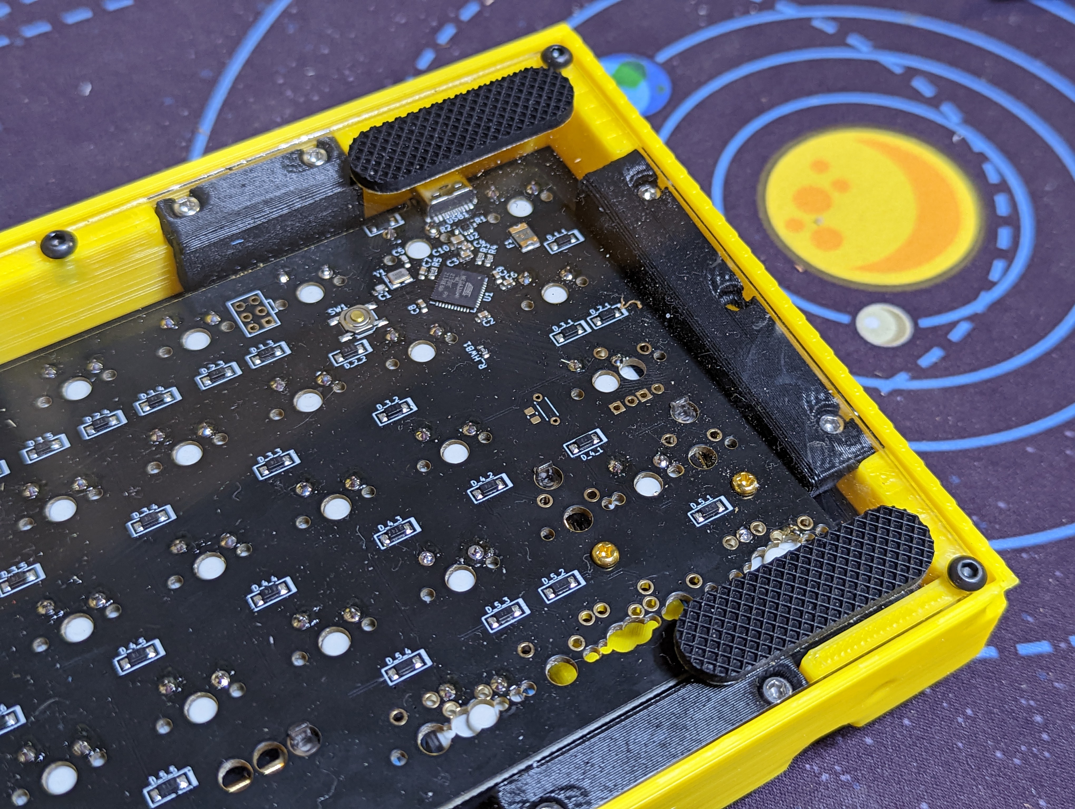
Add the remaining gaskets to the included brackets. Use the pictures to ensure proper orientation. The USB bracket gasket can be trimmed.
# Install the brackets
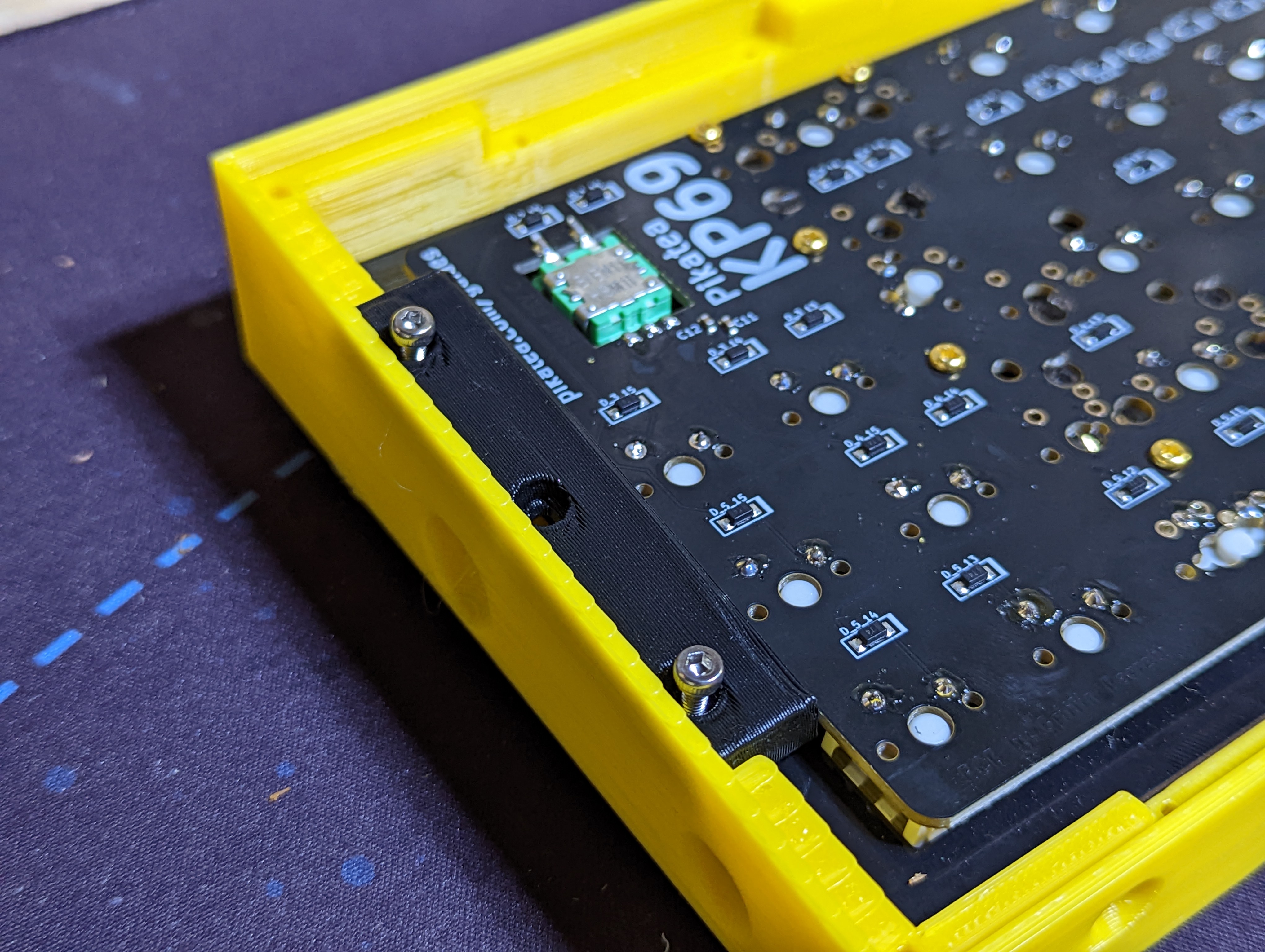
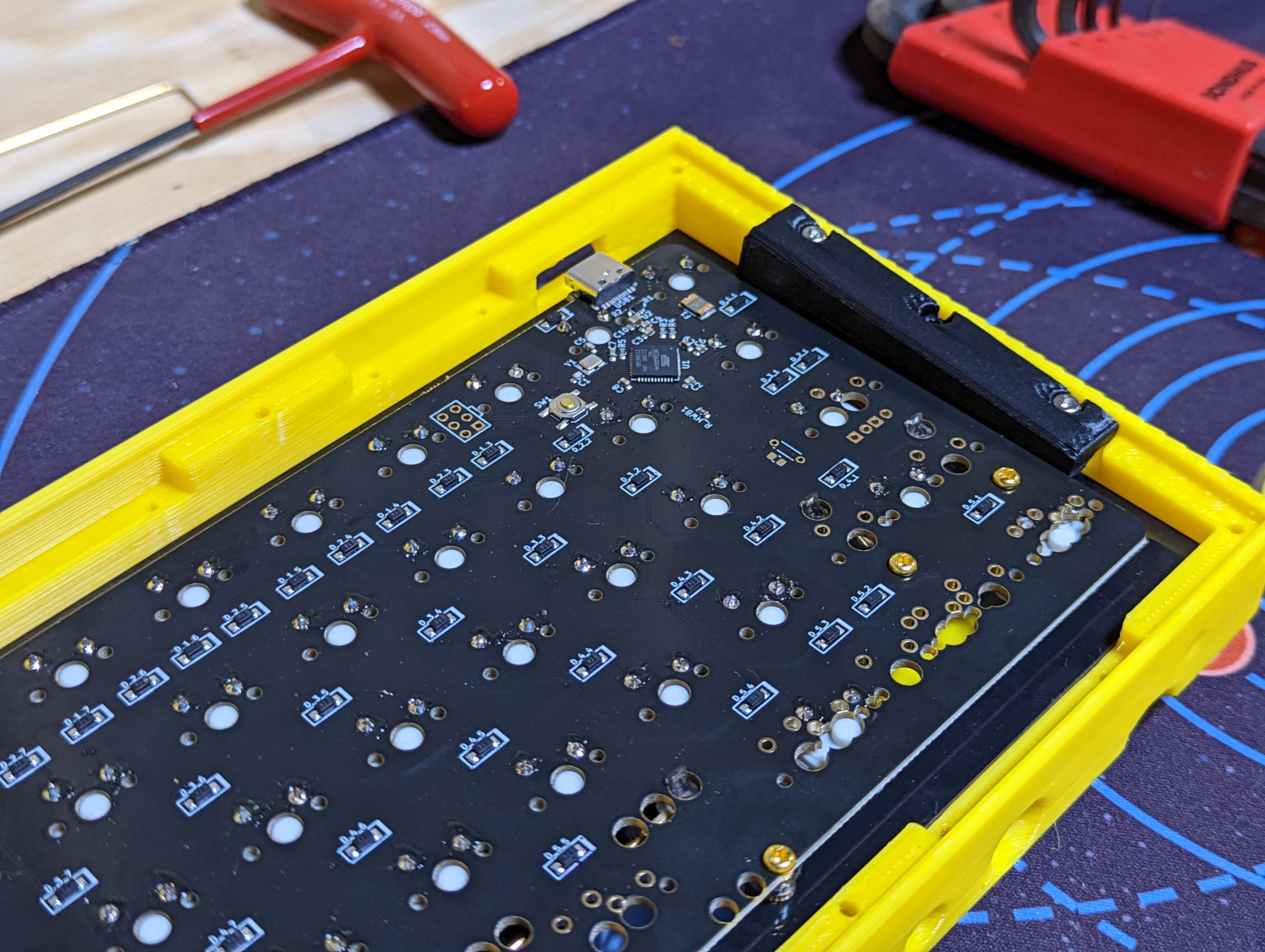
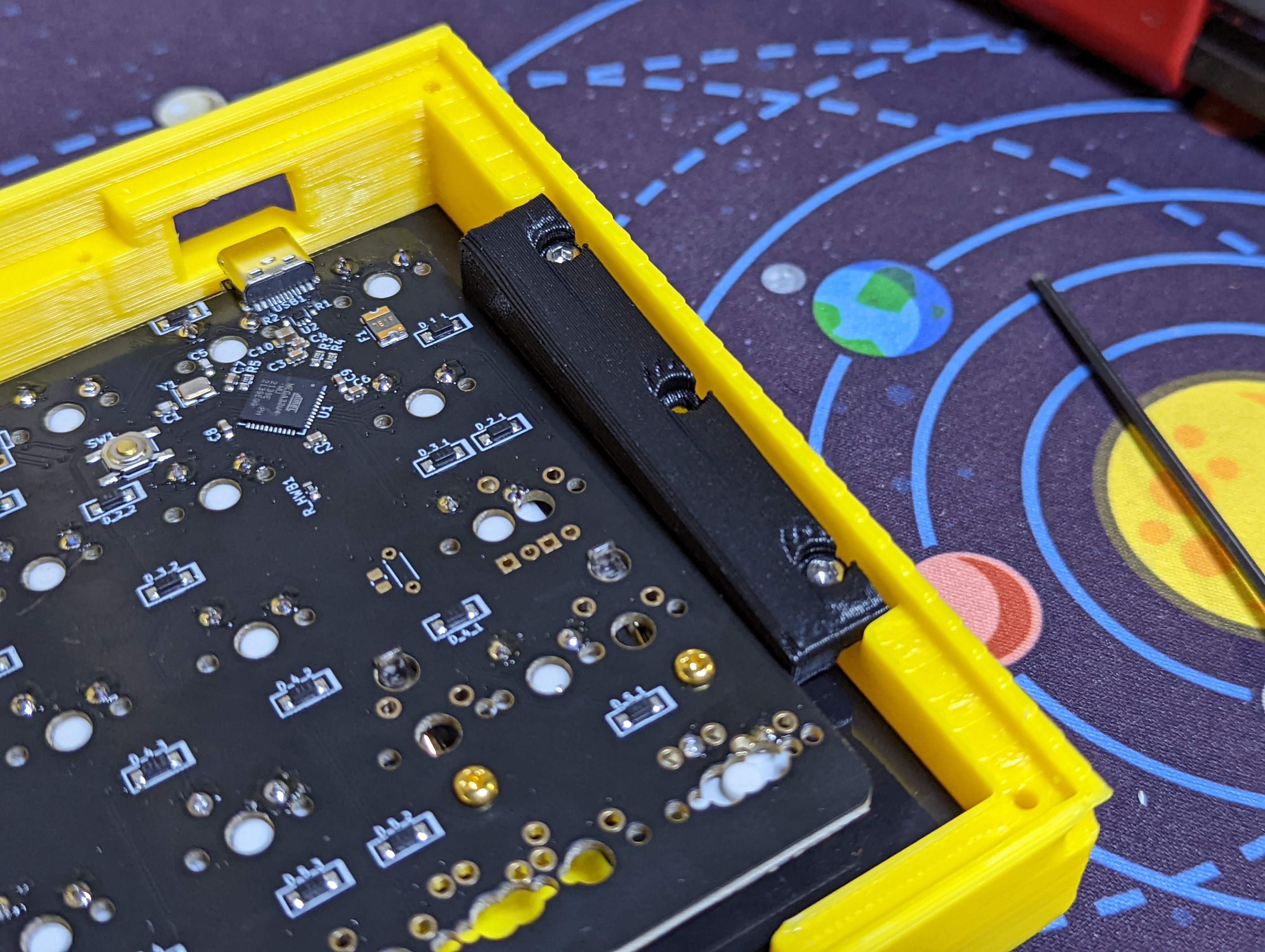
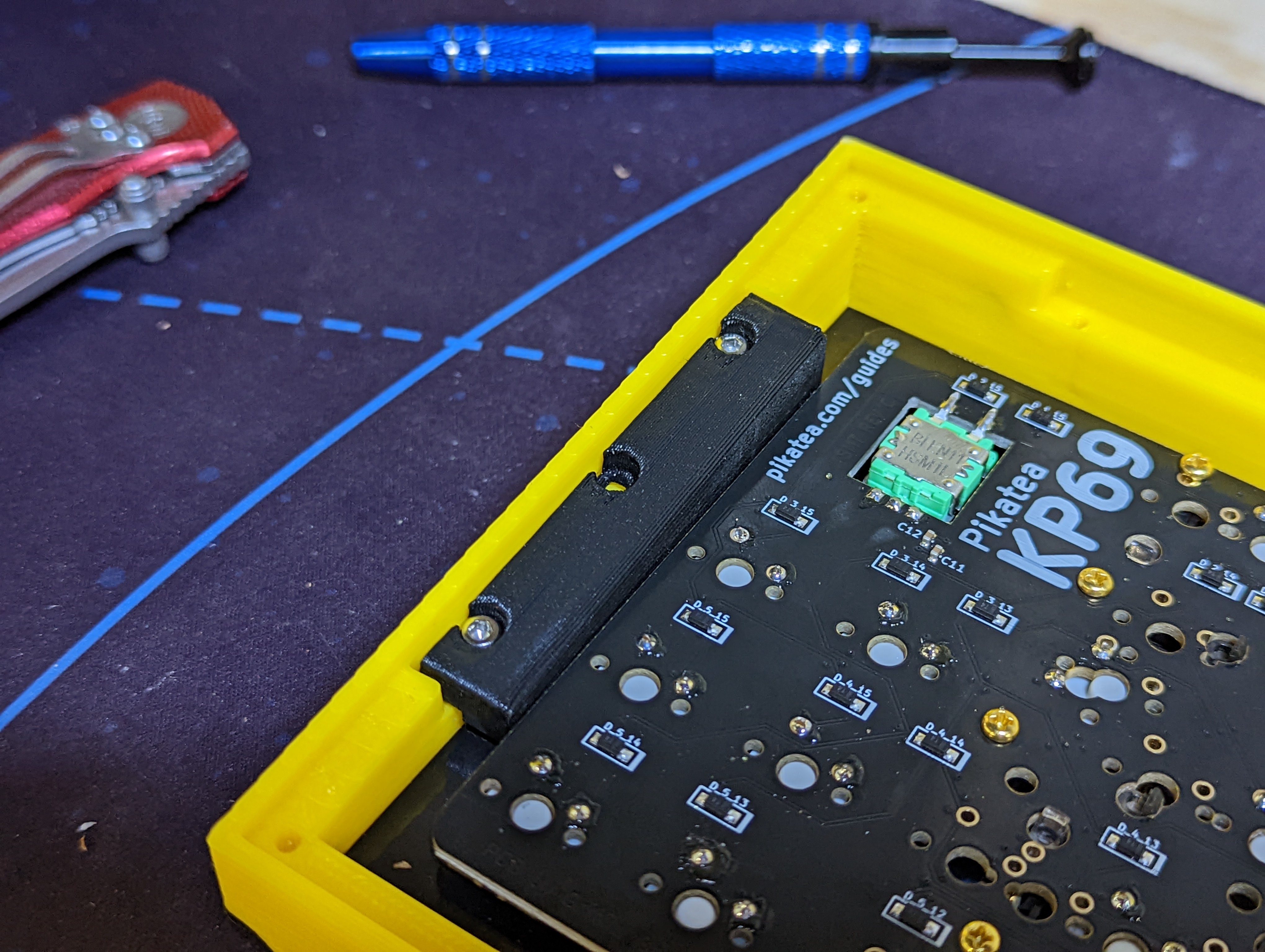
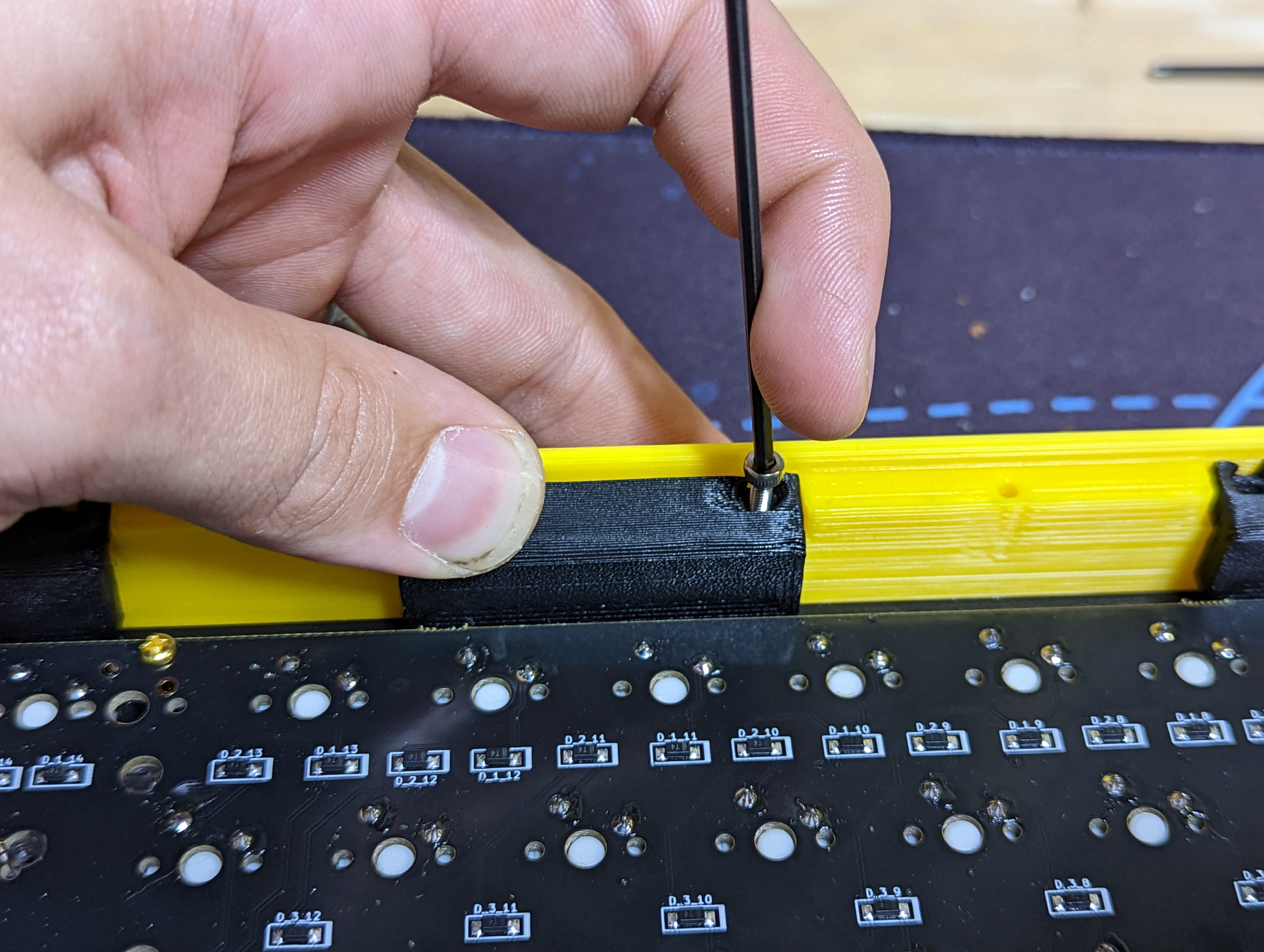
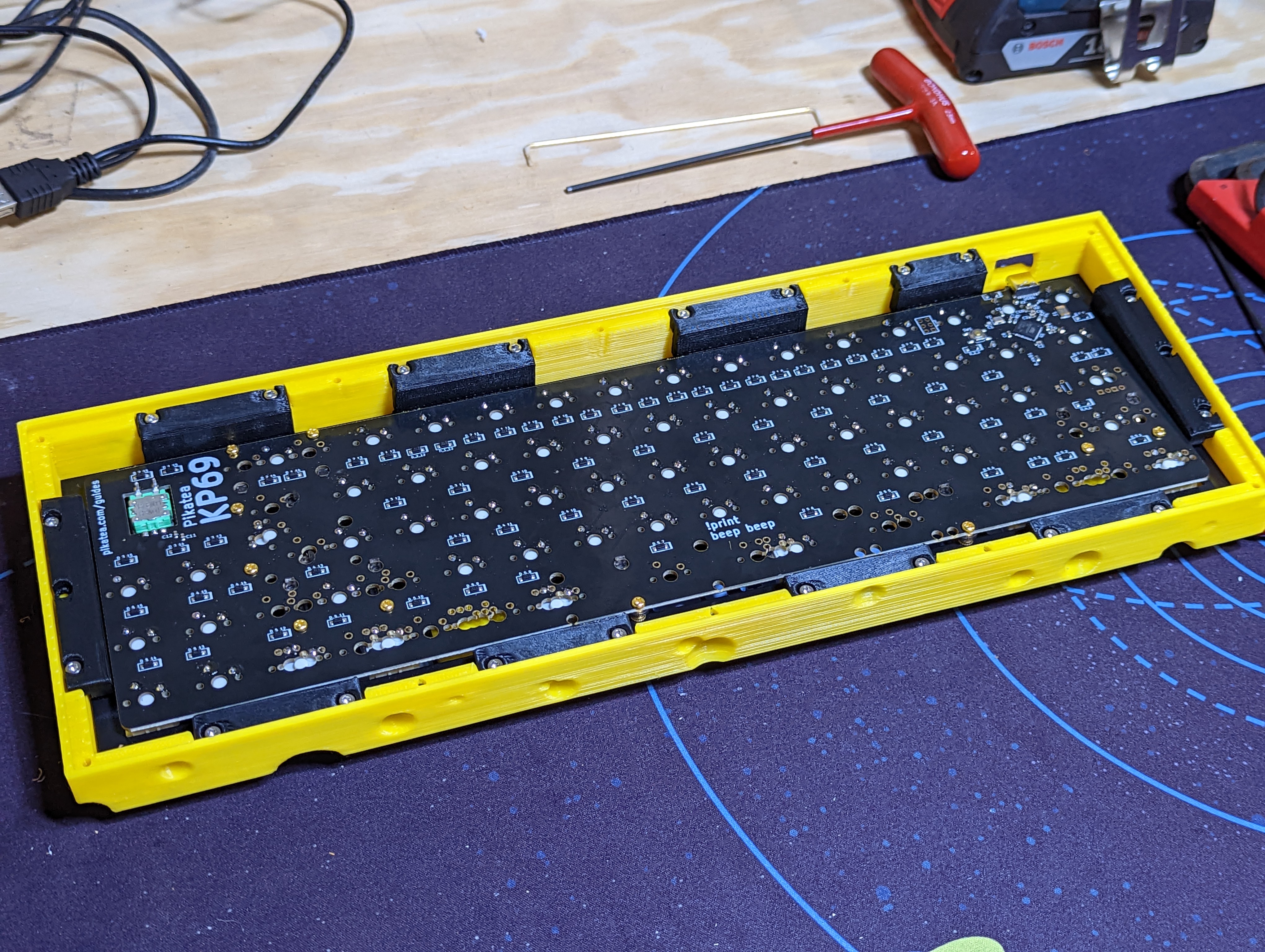
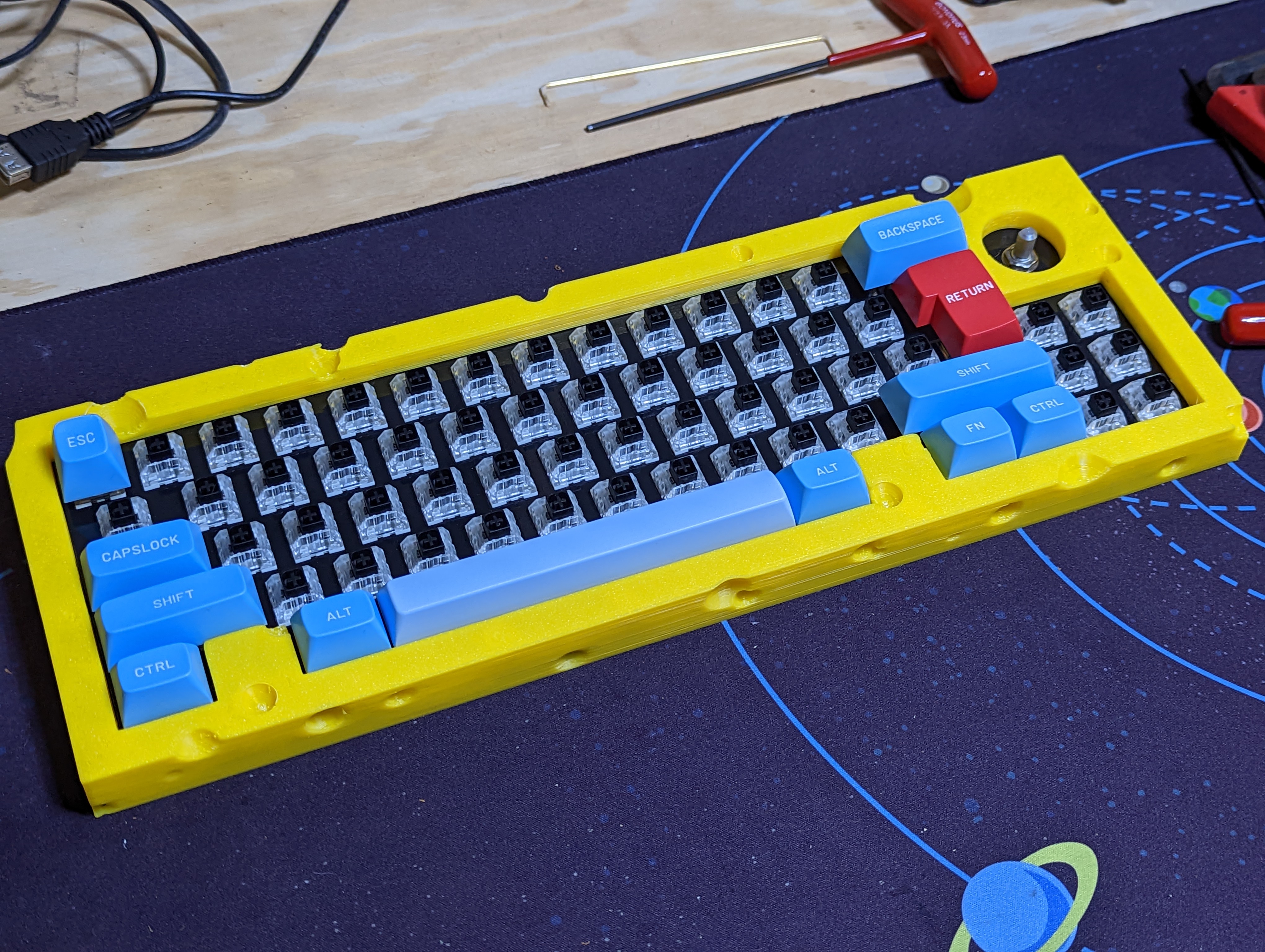
Place the assembled plate into the case and use the M2.5x10mm socket head screws to secure the side brackets to the case. After installing the side brackets, install the remaining brackets of your choice. You don't have to install them all!
# Install the backside cover and feet
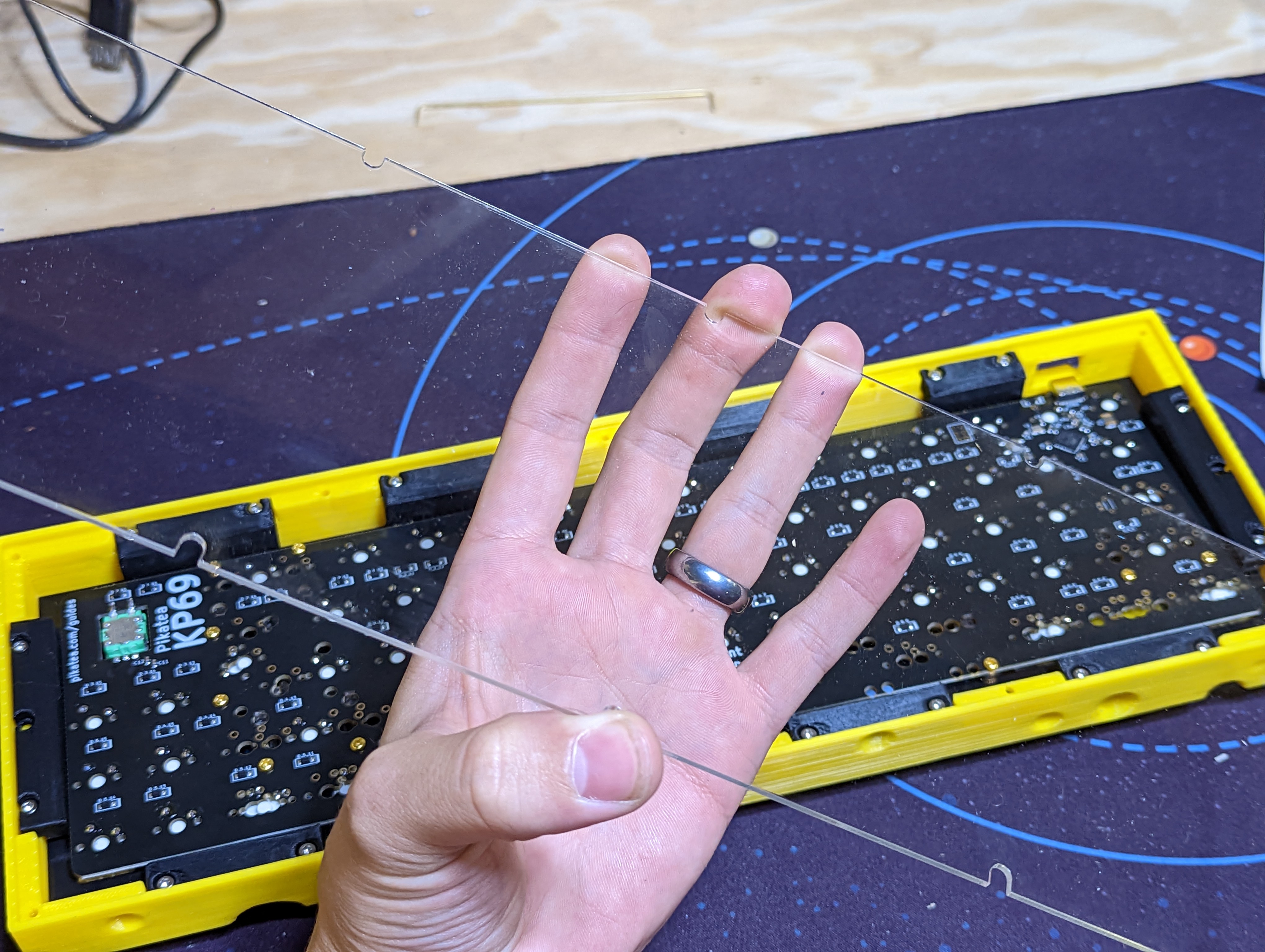
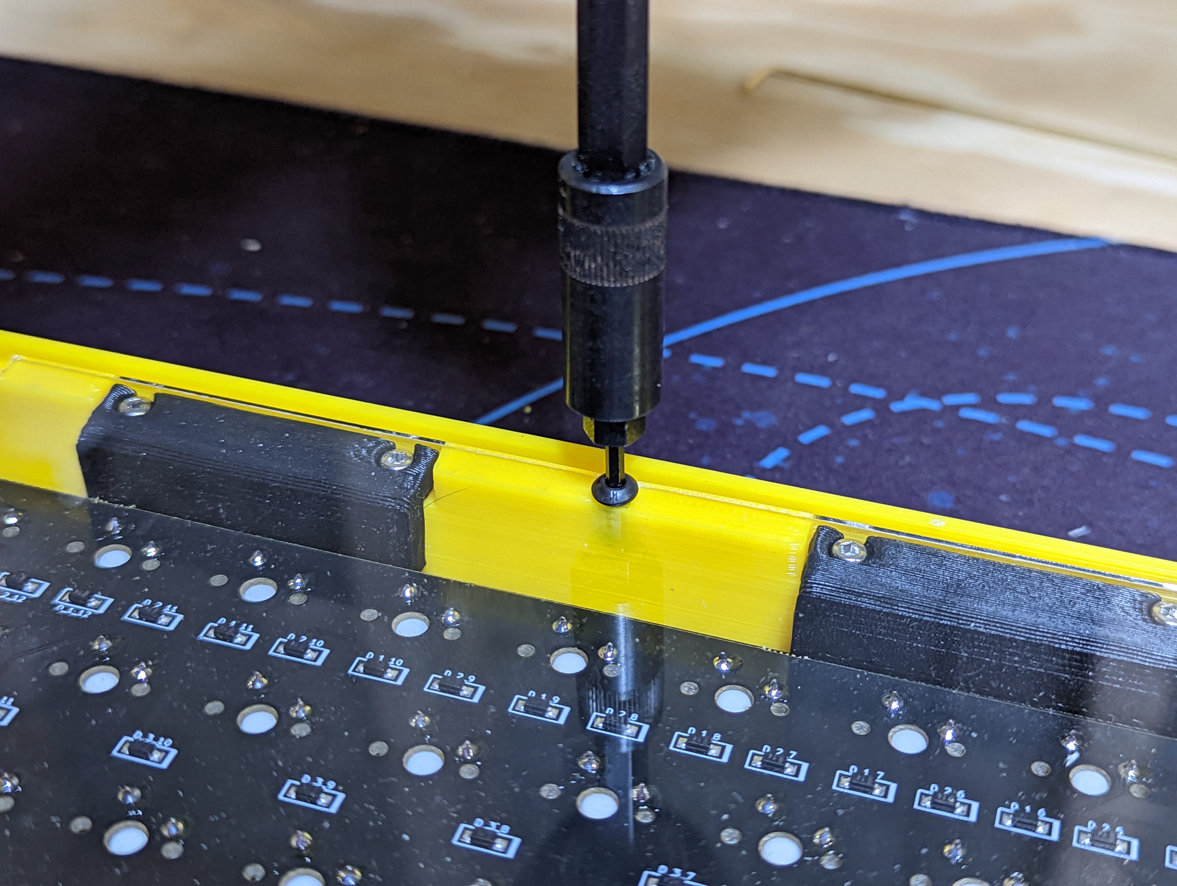
Peal the protective backing from the acrylic backside cover. Use the M3x8mm button head bolts to secure it to the back of the case. Stick the keyboard feet to the back wherever you like.
# Done!
Celebrate. It's required.
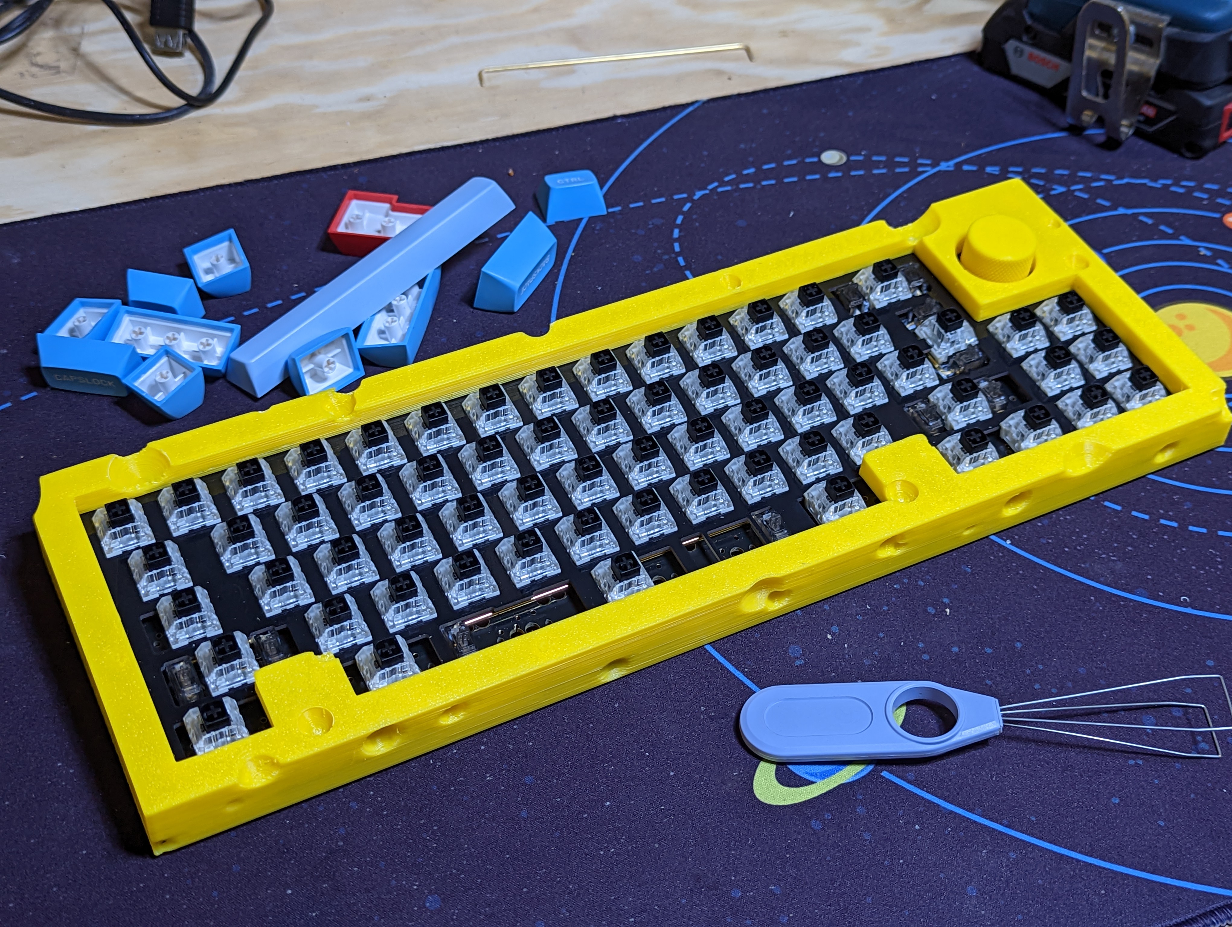
Follow the programming guide for instructions on using and programming your keyboard.
# Troubleshooting
Please ask on discord or email support if you have any other issues in regards to the assembly process.
