# Pikatea Macropad FK1 Assembly Guide
Congratulations on receiving your Pikatea Macropad FK1. This guide will walk you through the assembly process. Please make sure the read through the entire thing before getting started. Please email support or ask on Discord if you have any questions.
Here is a video for those that prefer it.
# What's in the Box
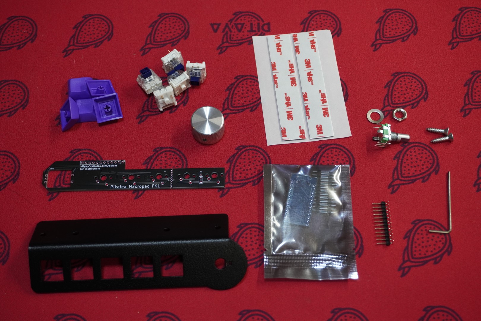
- (1) Top plate
- (1) Circuit board
- (1) Angled headers
- (1) MCU (Microcontroller)
- (1) Rotary encoder with hardware (washer and nut)
- (1) 1/16th inch Allen wrench
- (2) Screws for mounting
- (2) Pieces of mounting tape
- (5) Mechanical keyboard switches (if part of the order)
- (5) Keycaps (if part of the order)
- (1) Knob (if part of the order)
# Gather Required Materials
You will need everything that comes with the kit as well as a few other items. Those additional items include:
- Soldering iron and solder
- Tape
- Snips, metal cutter, or wire cutters. (technically optional but recommend)
- Pliers, adjustable wrench or 10mm size socket/wrench for the rotary encoder hardware.
- Extra cardboard. We recommend using the box your kit came in.
Now that you have everything you need, lets get started!
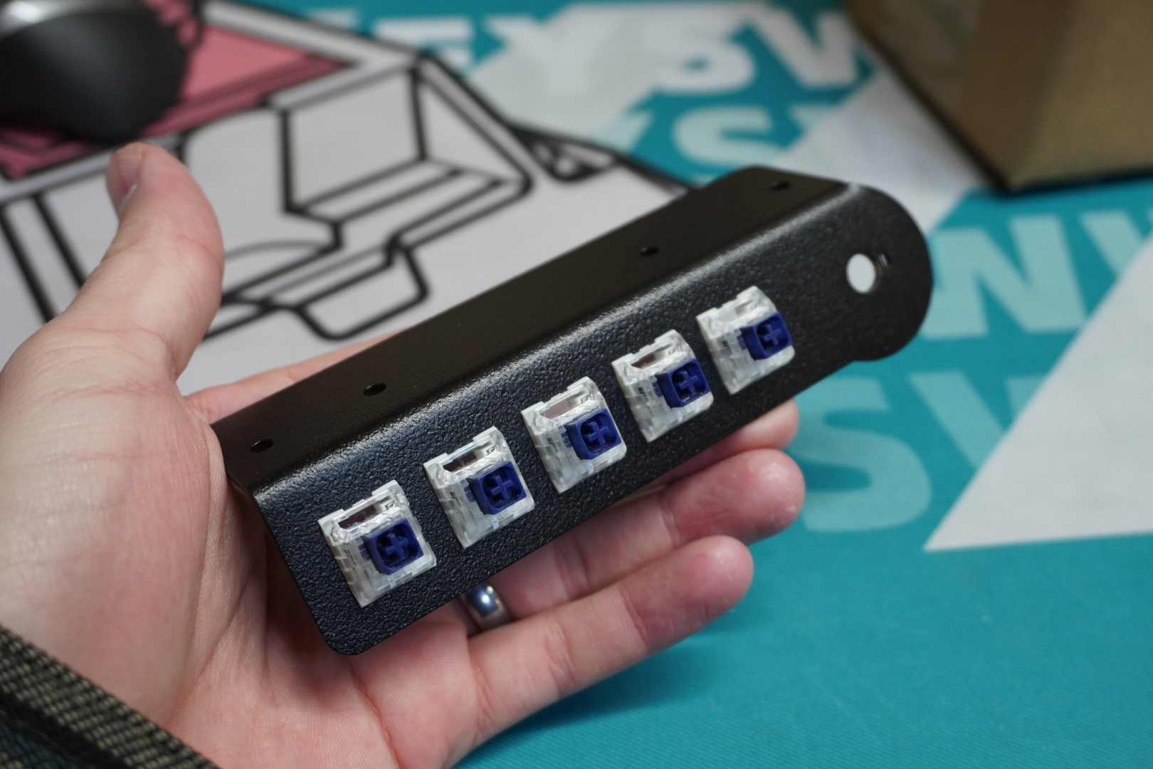
# Install the Mechanical Keyboard Switches
The mechanical keyboard switches need to be installed in a specific orientation. The LED slots face north or upwards when looking at the plate from the front. Make sure they snap into place and are flush with the top plate.
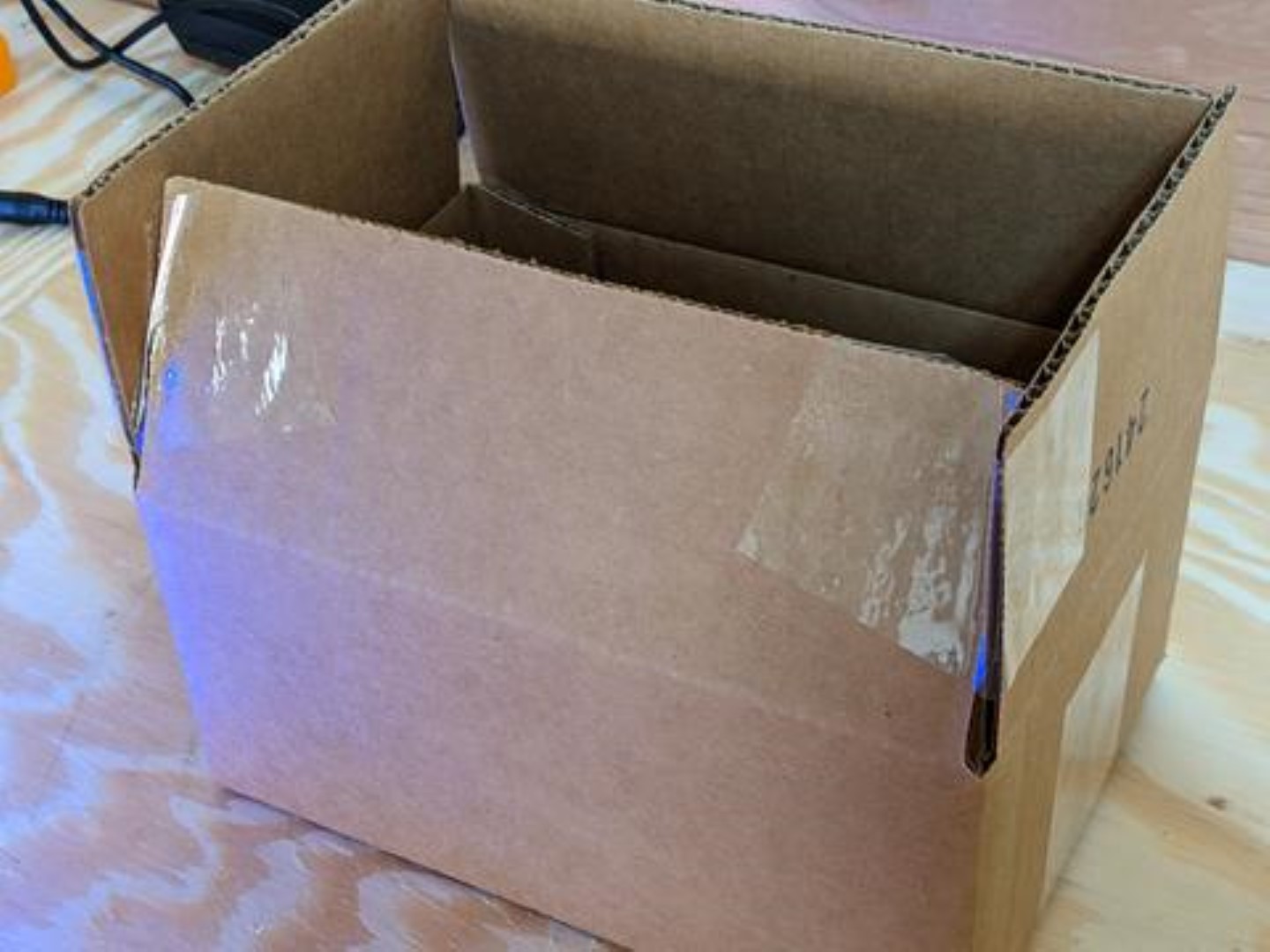
# Setup the Soldering Jig
Use a cardboard box (we recommend the box your kit came in) and tape one of the flaps so that it is at a 30 degree angle. Don't worry about this being precise or elegant, we are only using this to keep the macropad in the correct orientation for soldering without damaging the top plate surface.
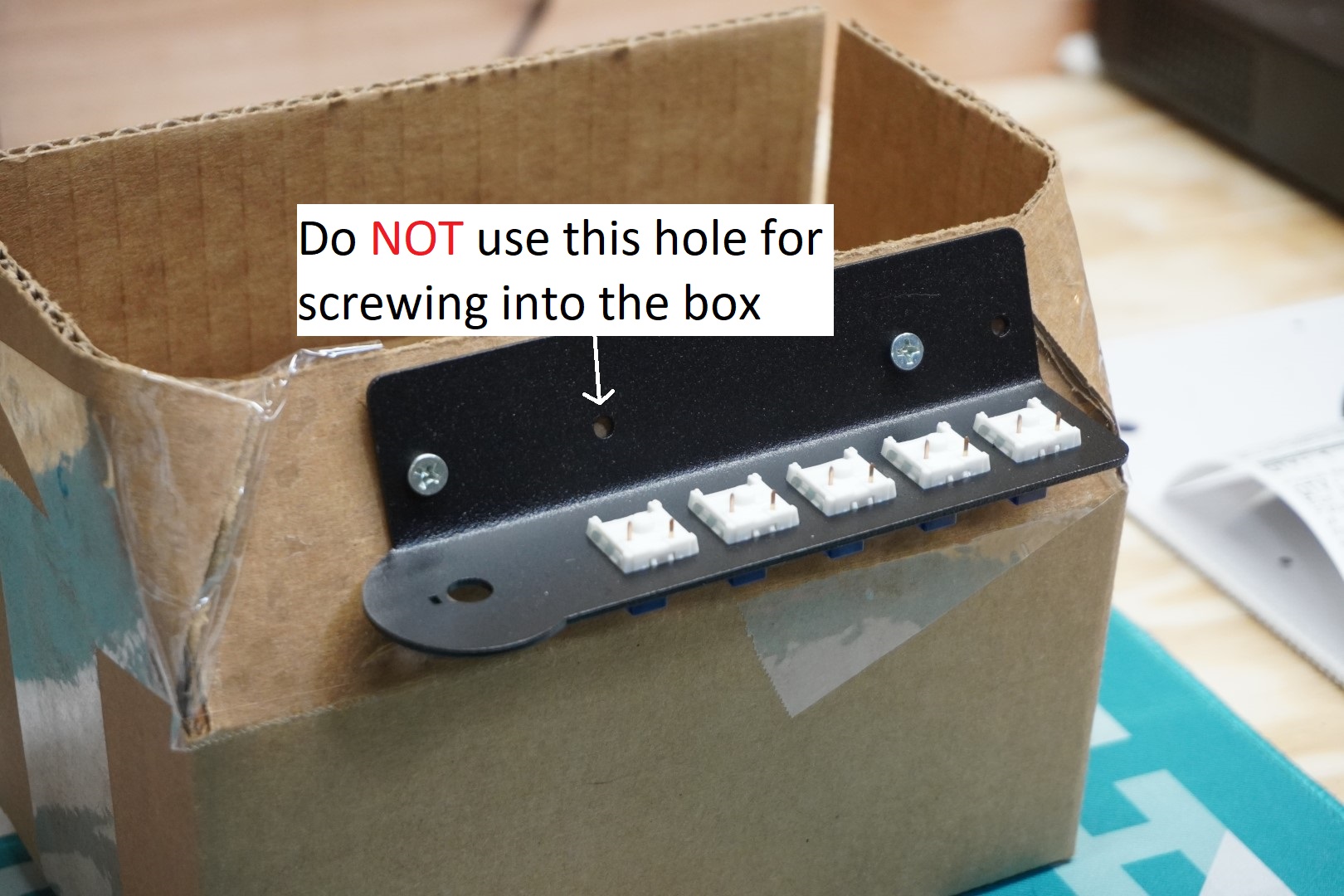
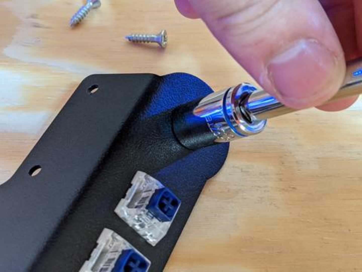
Use the screws that were included in the kit for mounting to attach your macropad to your angled cardboard surface. do NOT use the second hole or the screw will be stuck after soldering the pro micro. Place something heavy in the box like a book or a mug to make sure it doesn't tip over while soldering.
# Flash the MCU
You will want to flash the MCU before any soldering to make sure that it works.
Download the latest firmware (opens new window) file (.uf2). Download and install the latest version of Vial from https://get.vial.today (opens new window). While holding the boot button on the MCU, plug it into a computer. There should be a new directory that shows up on the computer. Copy the .uf2 file to this directory. The MCU should automatically disconnect but unplug and re-plug in the MCU anyways. Open Vial and verify that you can see "Pikatea Macropad FK1" at the top before continuing. Contact us through support or Discord before continuing if you are encountering issues.
If your MCU is blue, and/or you ordered your kit before December 7th 2023, please follow this guide instead
# Prepare the Circuit Board
Read this whole section before soldering.
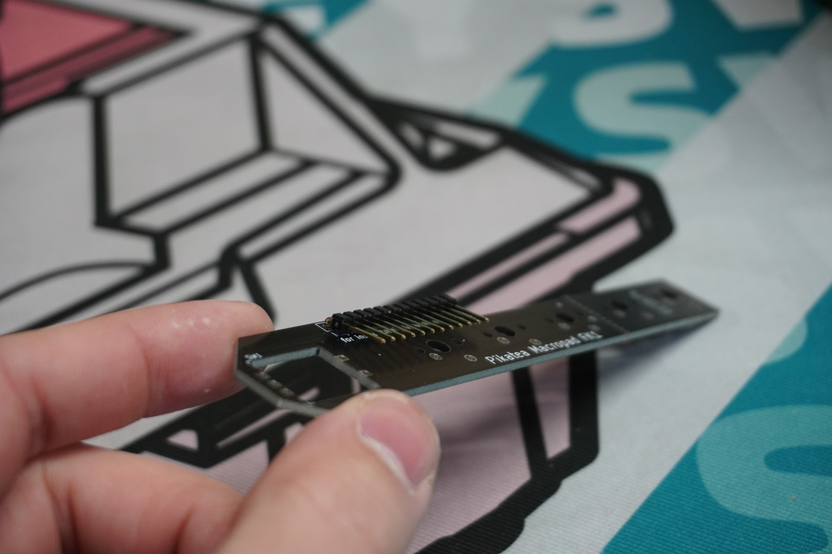
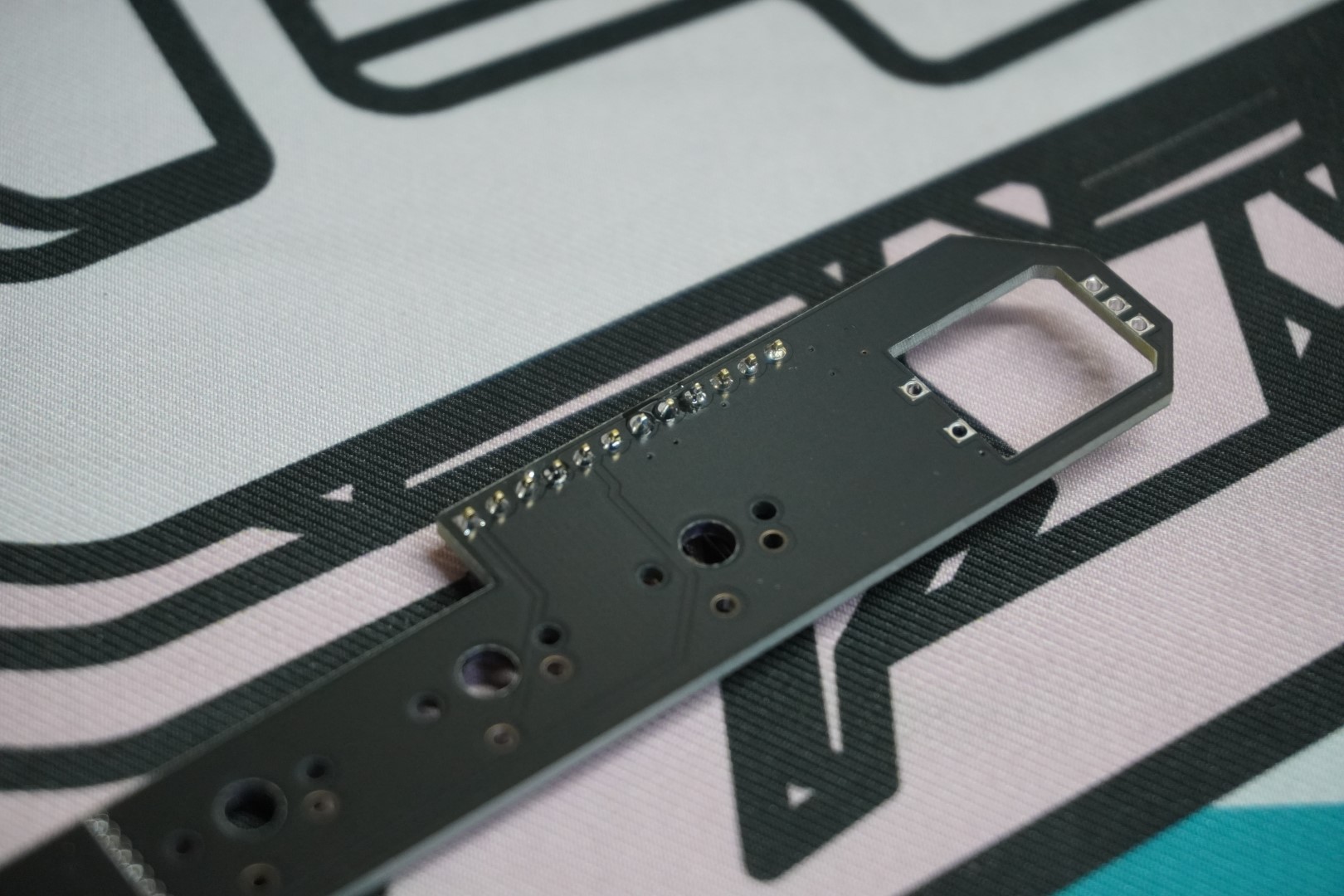
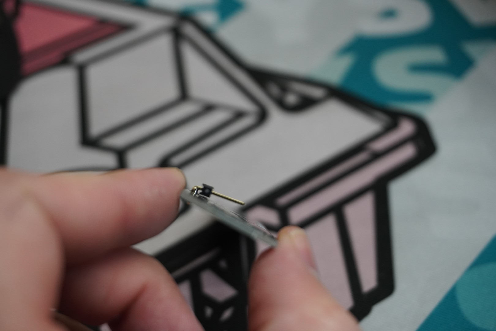
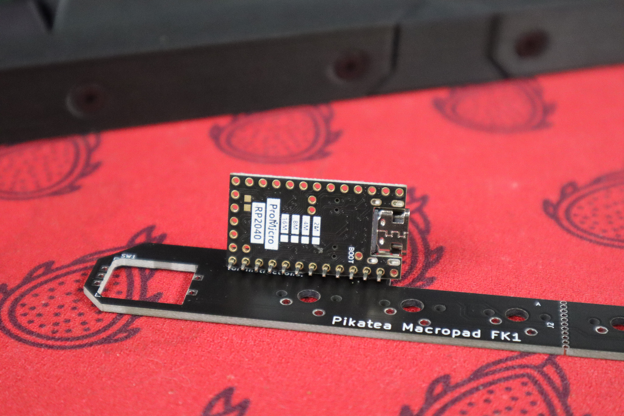
Start with the angled header. Place the angled header onto the circuit board as shown below. Solder ONE of the middle pins and ensure it's at the correct angle before soldering the rest. You can reflow the middle joint if the angle is not correct. Slide the Pro Micro onto the pins to test the angle is good.
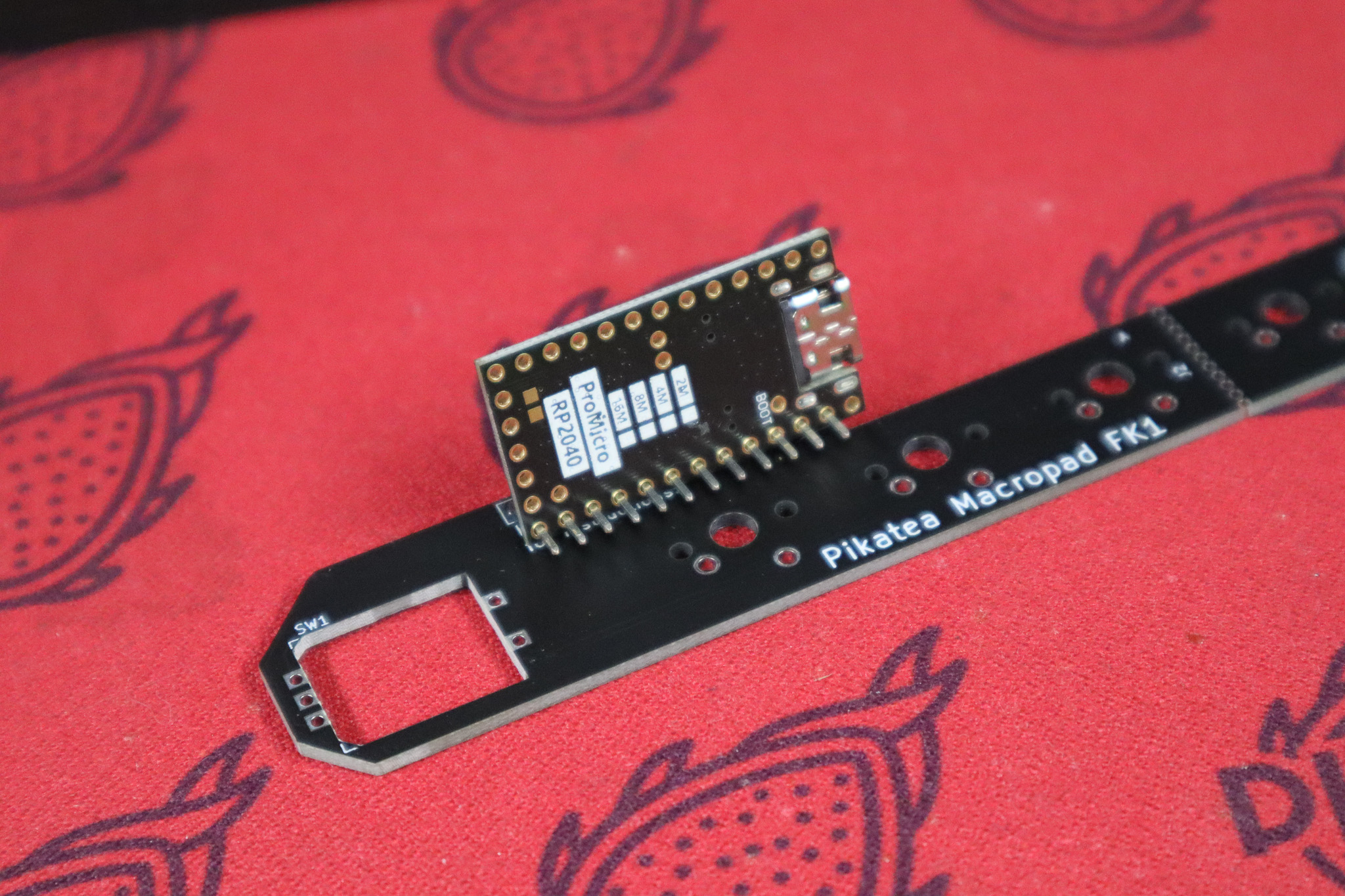
Next, solder the Pro Micro onto the angled header. Be careful to get the orientation correct. Like before, start with the middle pin and reflow it and adjust the fit if necessary.
# Solder the PCB to the switches
Place the PCB onto the switches and solder the switches onto it. Make sure to get them all!
# Install the Rotary Encoder
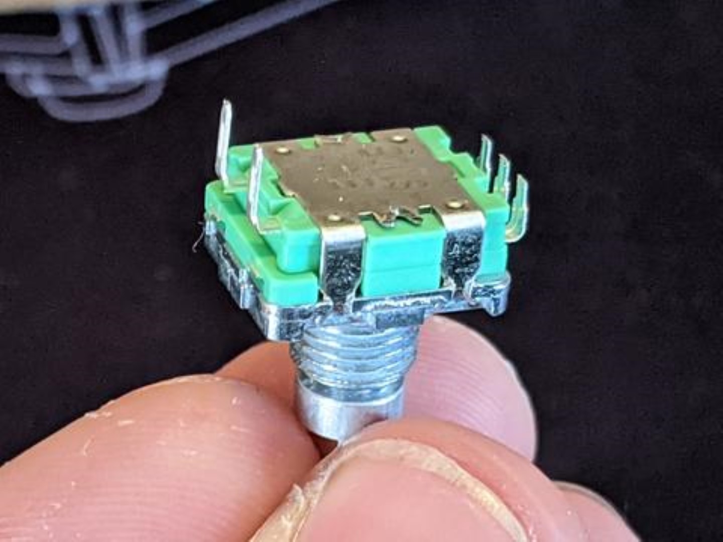
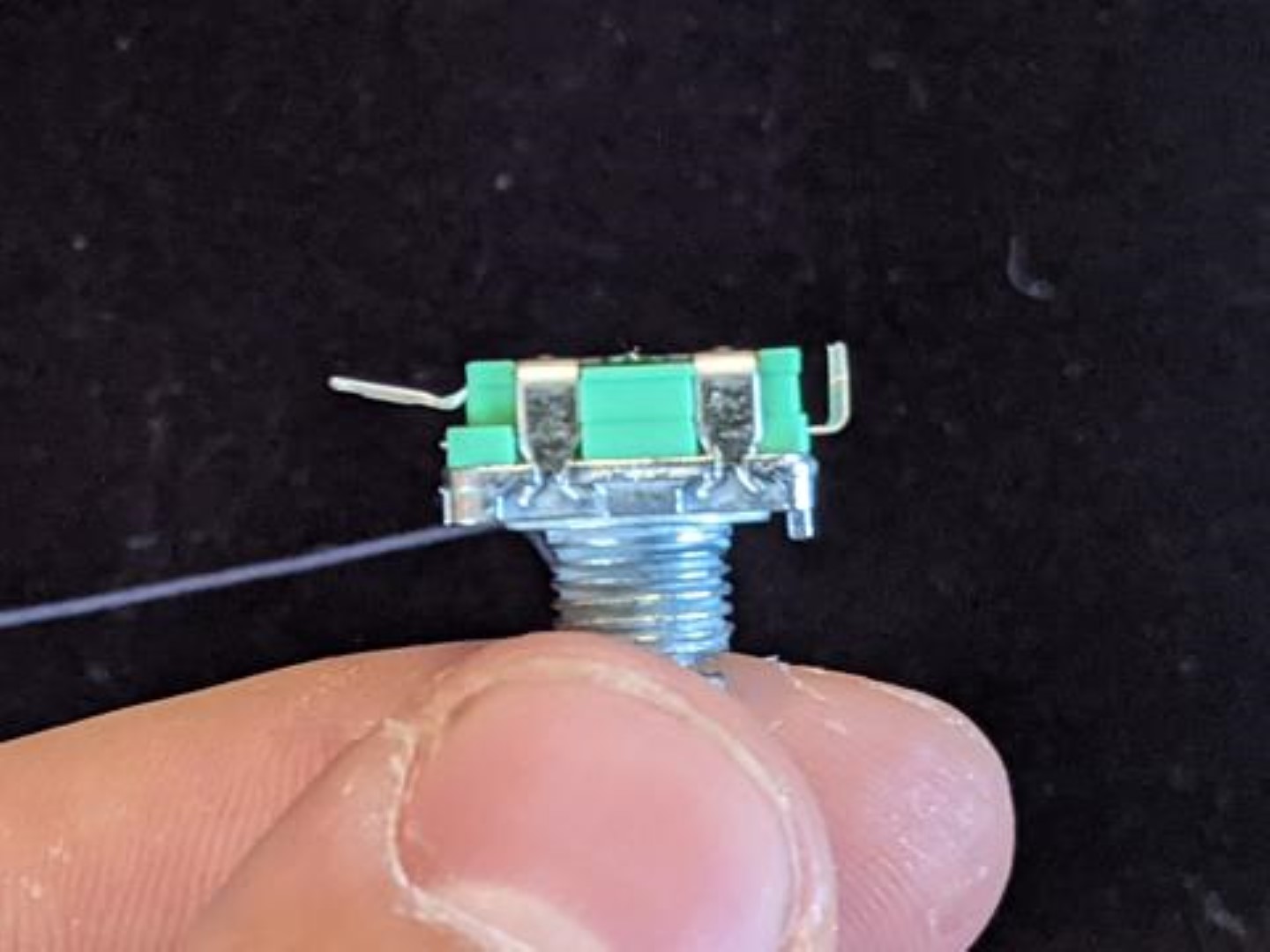
Next up is the rotary encoder. Prep the rotary encoder by snipping the mounting tabs with snips or wire cutters. Cut the set of 3 pins shorter so they are flush with the bottom of the rotary encoder. Lastly, bend the set of 2 pins so they are pointing straight out with a slight angle.
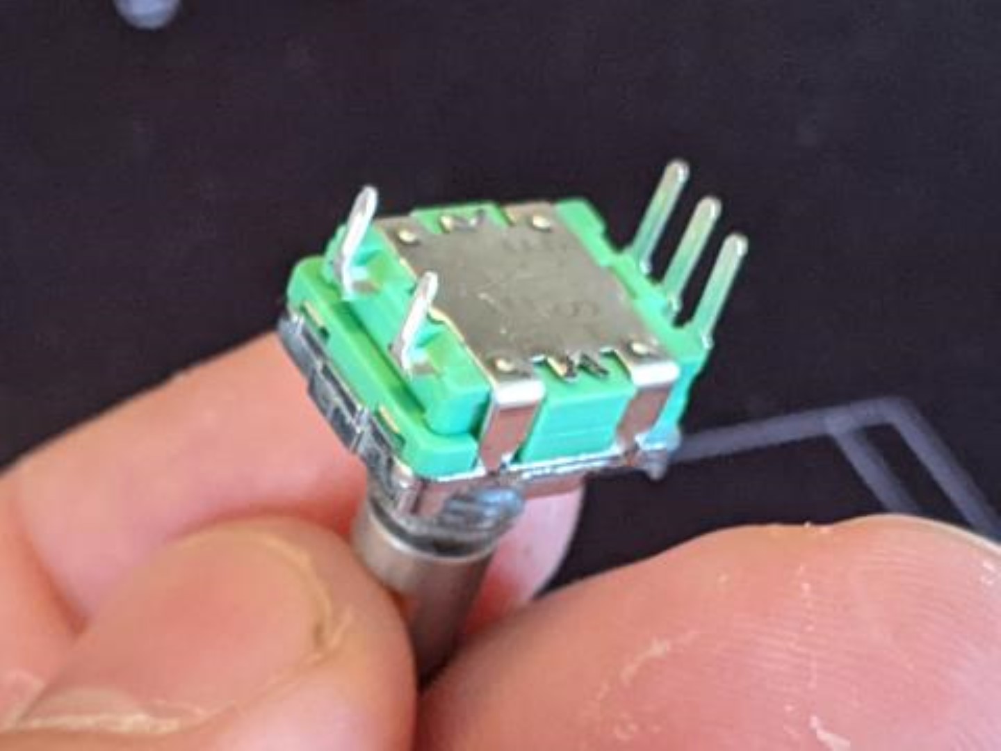
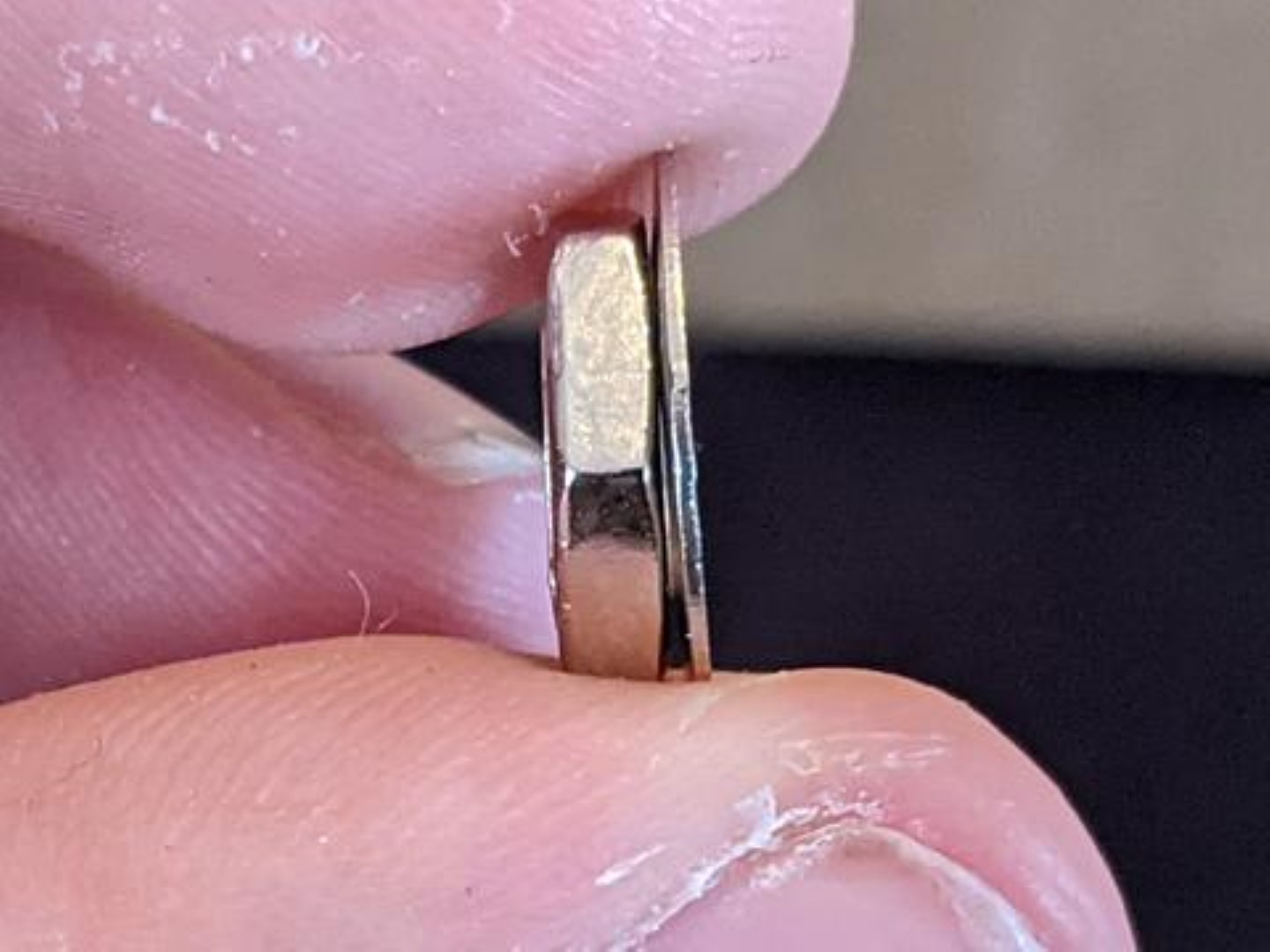
Place the rotary encoder in the hole of the top plate and hand tighten the washer and nut to hold it in place for soldering. Don't tighten this with any tools just yet. The washer has a slight bend in it so be careful to place the raised part in the center facing towards the front of the macropad. Use the pictures shown to ensure the correct orientation.
# Solder the Rotary Encoder
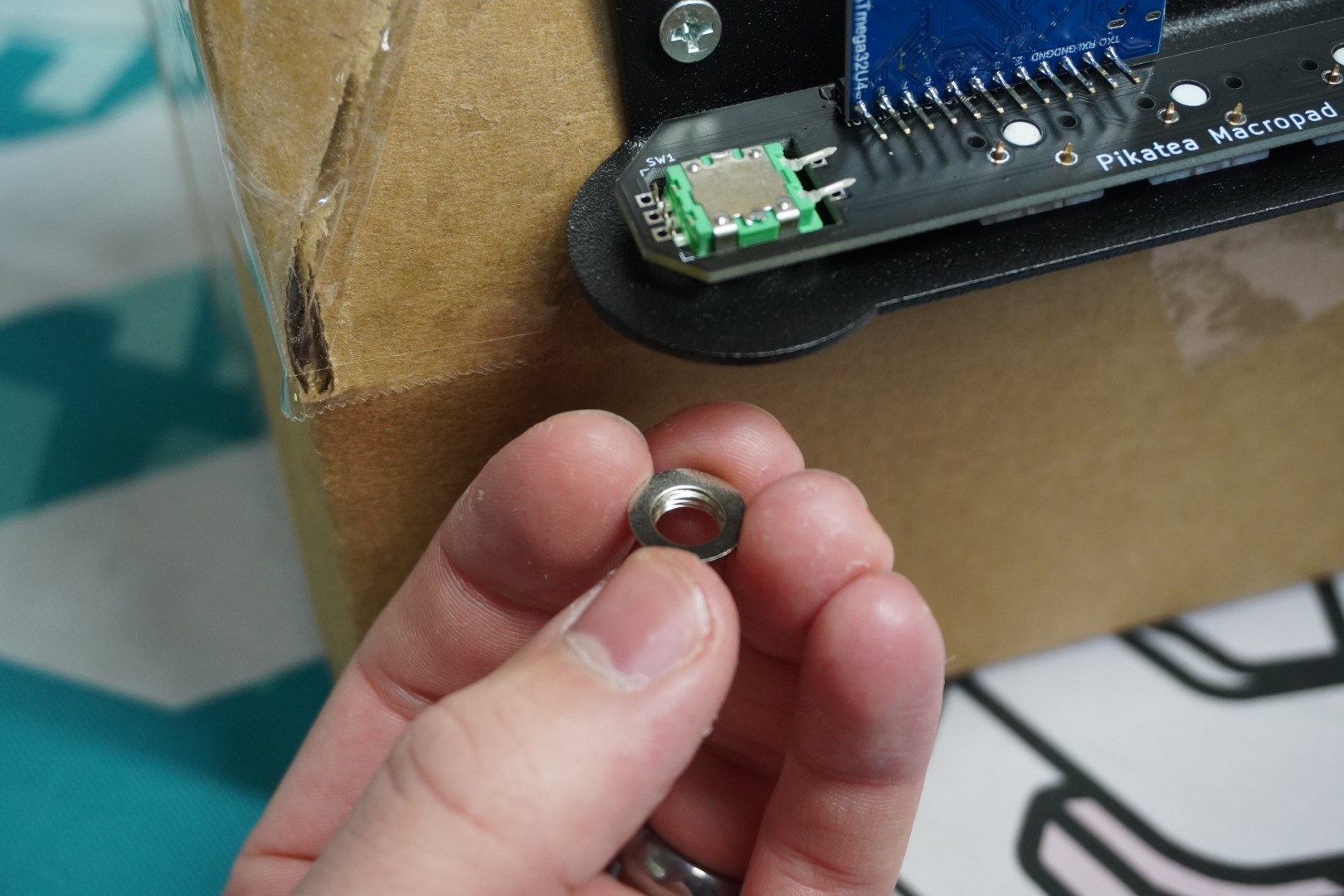
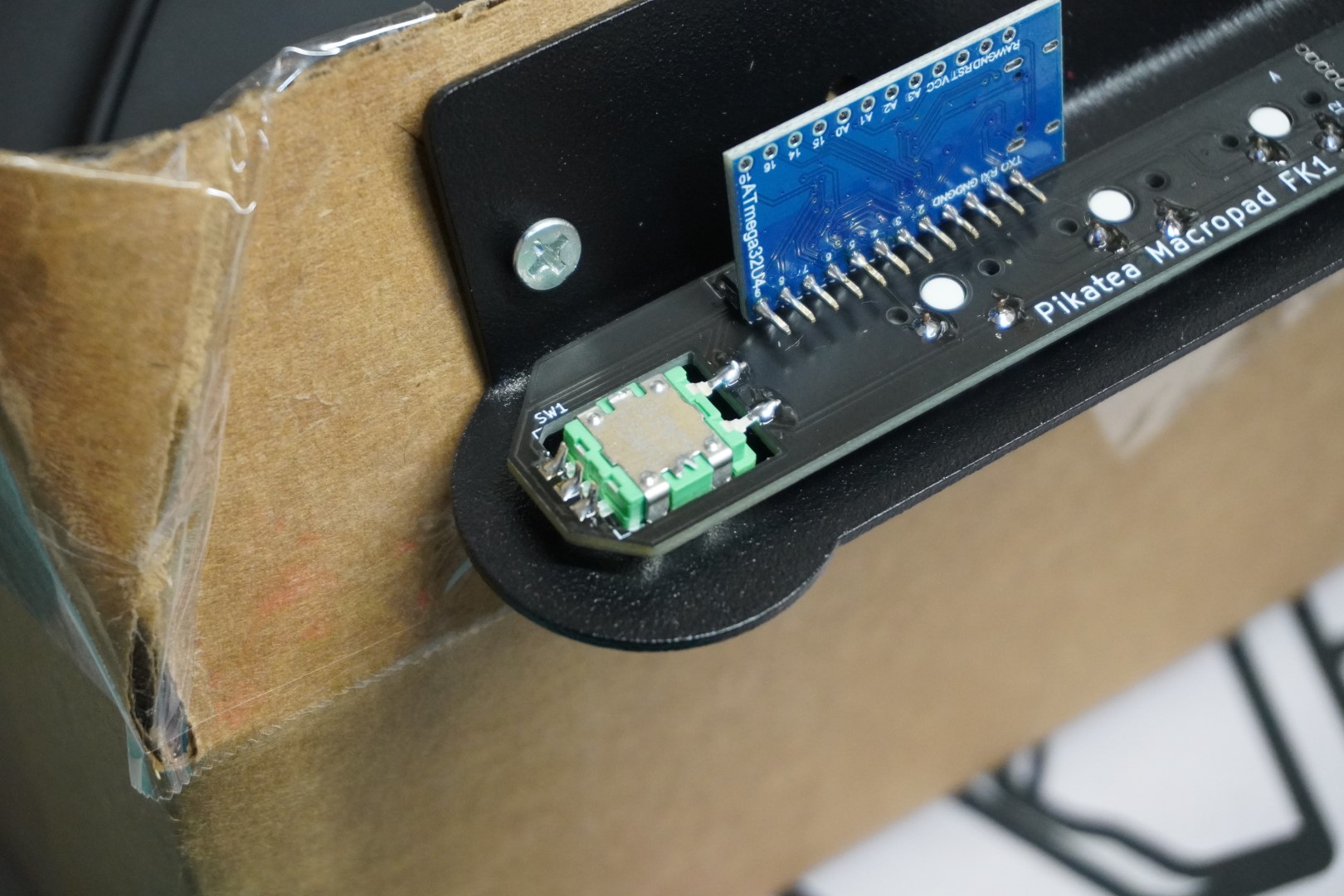
After the rotary encoder is in place, it is time to solder it. The 2 bent pins on the rotary encoder are resting just above the pads were they need to be soldered to, facing toward the switches. The 3 shorter pins on the rotary encoder are placed just to the side of the pads were they need to be soldered to. They do not go through the holes. Take a look at the picture shown for a better explanation.
# Tighten the Encoder and Attach the Knob
Unscrew the macropad from the box but save it incase there is something wrong when testing.
Tighten the encoder with a wrench, pliers or 10mm socket. Do not over tighten, especially if using a 3D printed top plate. Turning the nut about 1/4 of a full turn after hand tightening should fine for all plate materials.
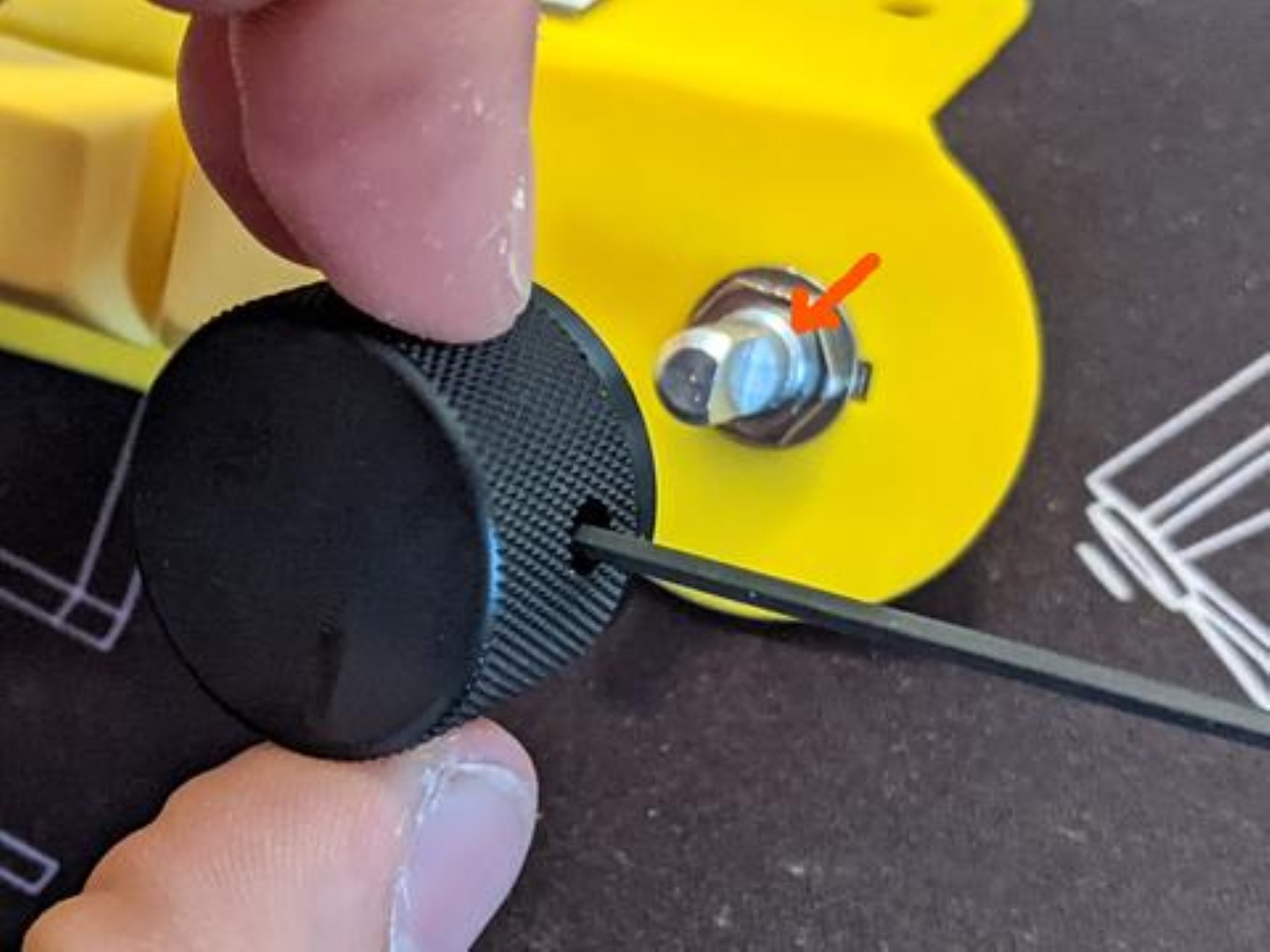
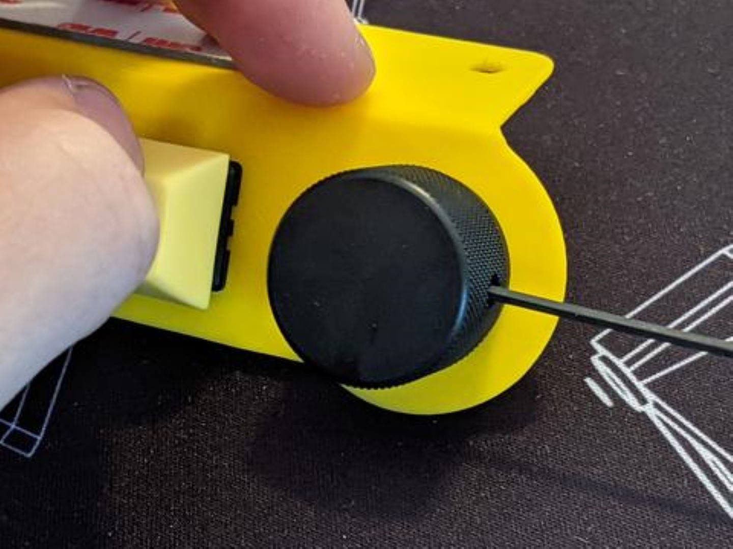
Use the Allen wrench included with the kit to bring the set screw inside the knob so that it barely pokes out. Place the knob on the encoder shaft so that the set screw interfaces with the flat part of the encoder shaft. After it is in place, tighten the set screw. Be careful not to over tighten with the 3D printed knobs or it will strip. Error on the side of too loose since it can be tightened later.
# Add the Keycaps
Add the keycaps to your macropad and click the switches a bunch because it's fun and satisfying.
# Test the Macropad BEFORE mounting
This is a very crucial step. The last thing you'd want to do is install your macropad only to realize you forgot to solder all the pins correctly.
Follow the programming guide but mount the device later after you've verified everything functions.
If everything works, Congrats! You did it!
# Troubleshooting
Q: The rotatary encoder rotation doesn't work. A: The set of 3 pins on the rotary encoder control the directional/rotational control of the knob. Reflow the set of 3 pins so they have a solid connection.
Please ask on discord or email support if you have any other issues in regards to the assembly process.