# Pikatea Macropad GB4 Assembly Guide
Congratulations on receiving your Pikatea Macropad GB4 Kit. This guide will walk you through the assembly process. Please email support or ask on Discord if you have any questions.
# What's in the Box
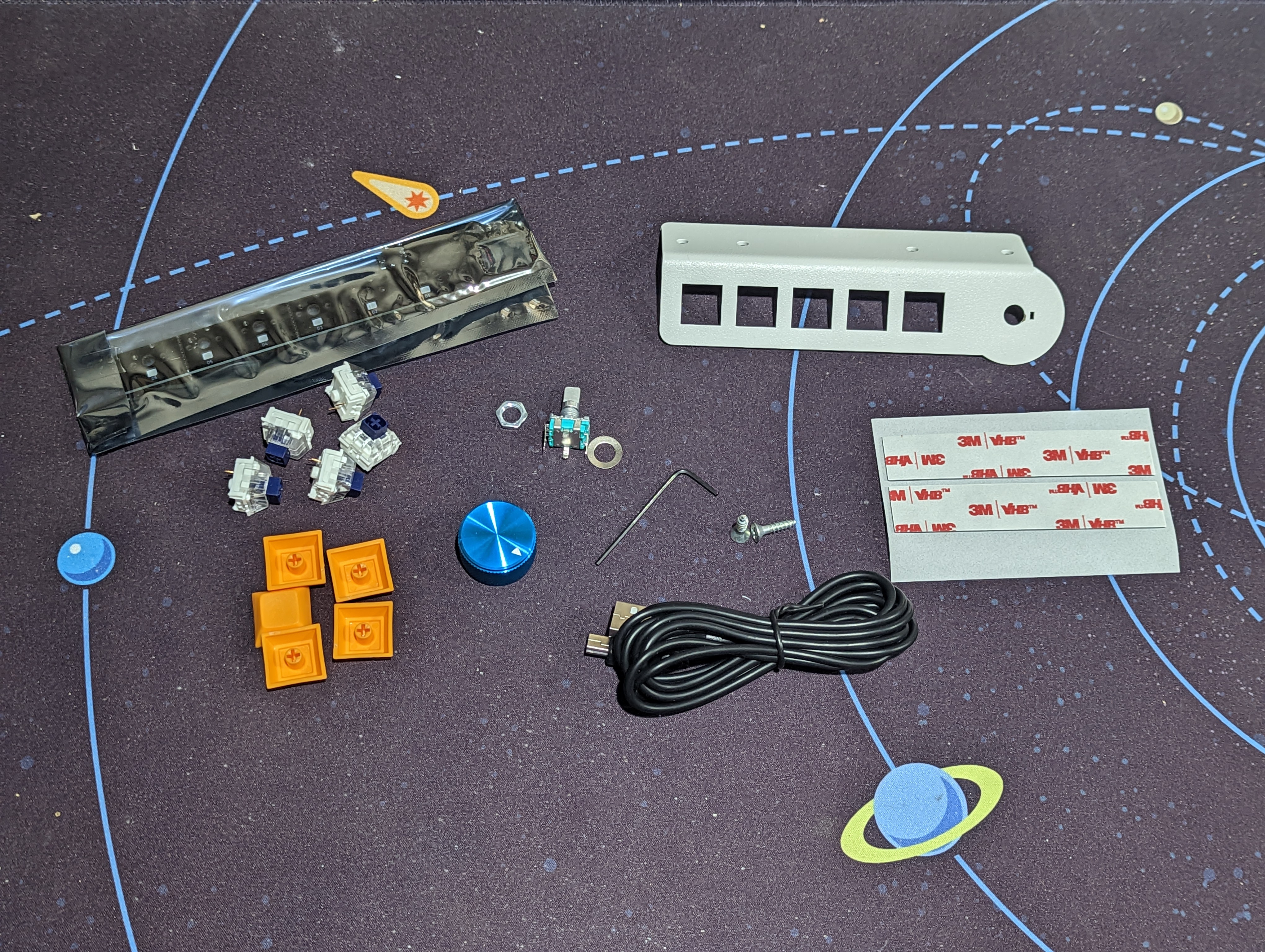
- (1) Top plate
- (1) Circuit board
- (3, 5 or 7) Mechanical keyboard switches
- (3, 5, or 7) Keycaps
- (1) Knob
- (1) Rotary encoder with hardware (washer and nut)
- (1) Allen wrench (1/16th inch)
- (2) Screws for mounting
- (1) USB cable
- (2) Pieces of mounting tape
# Gather Required Materials
You will need everything that comes with the kit as well as a few other items. Those additional items include:
- Soldering iron and solder
- Tape
- Flush cut Snips (recommended), metal cutters, or wire cutters.
- Screw driver
- Pliers, adjustable wrench or a 10mm socket
- Extra cardboard. We recommend using the box your kit came in.
Now that you have everything you need, let's get started!
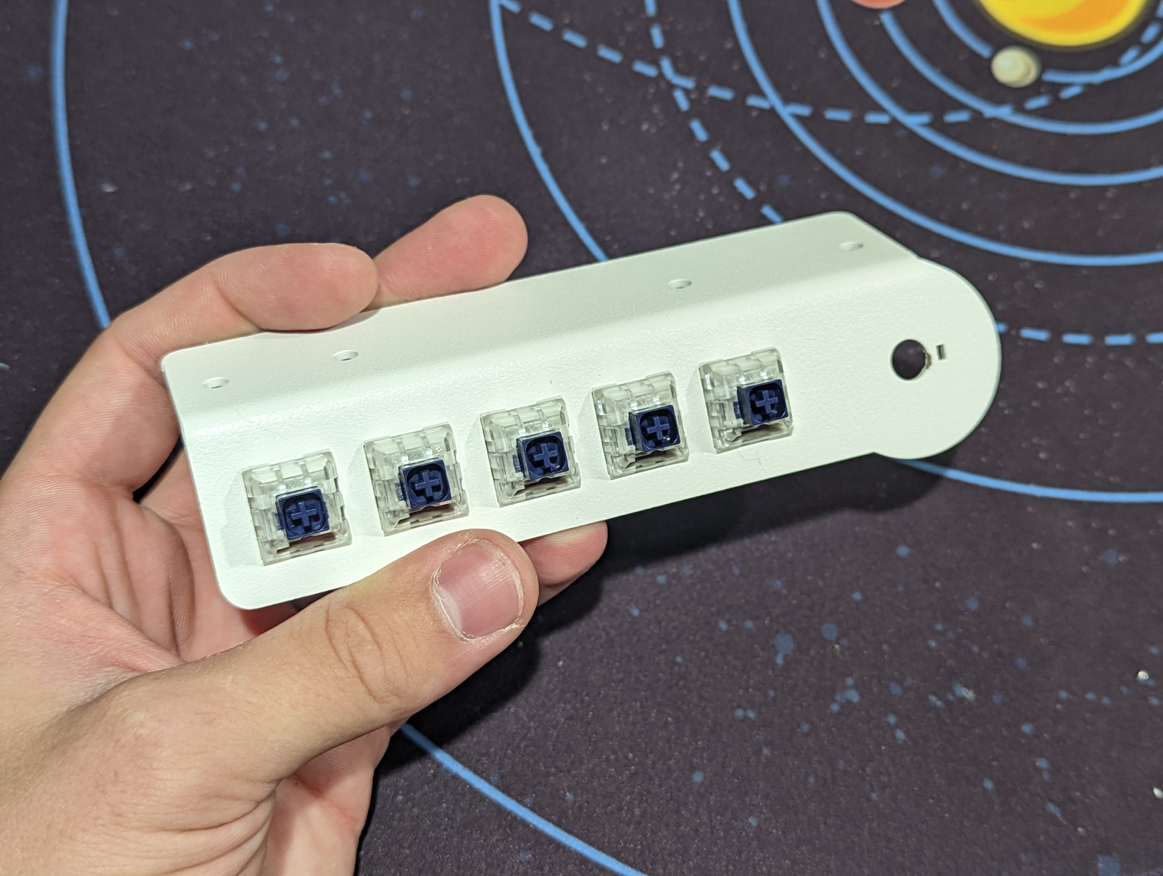
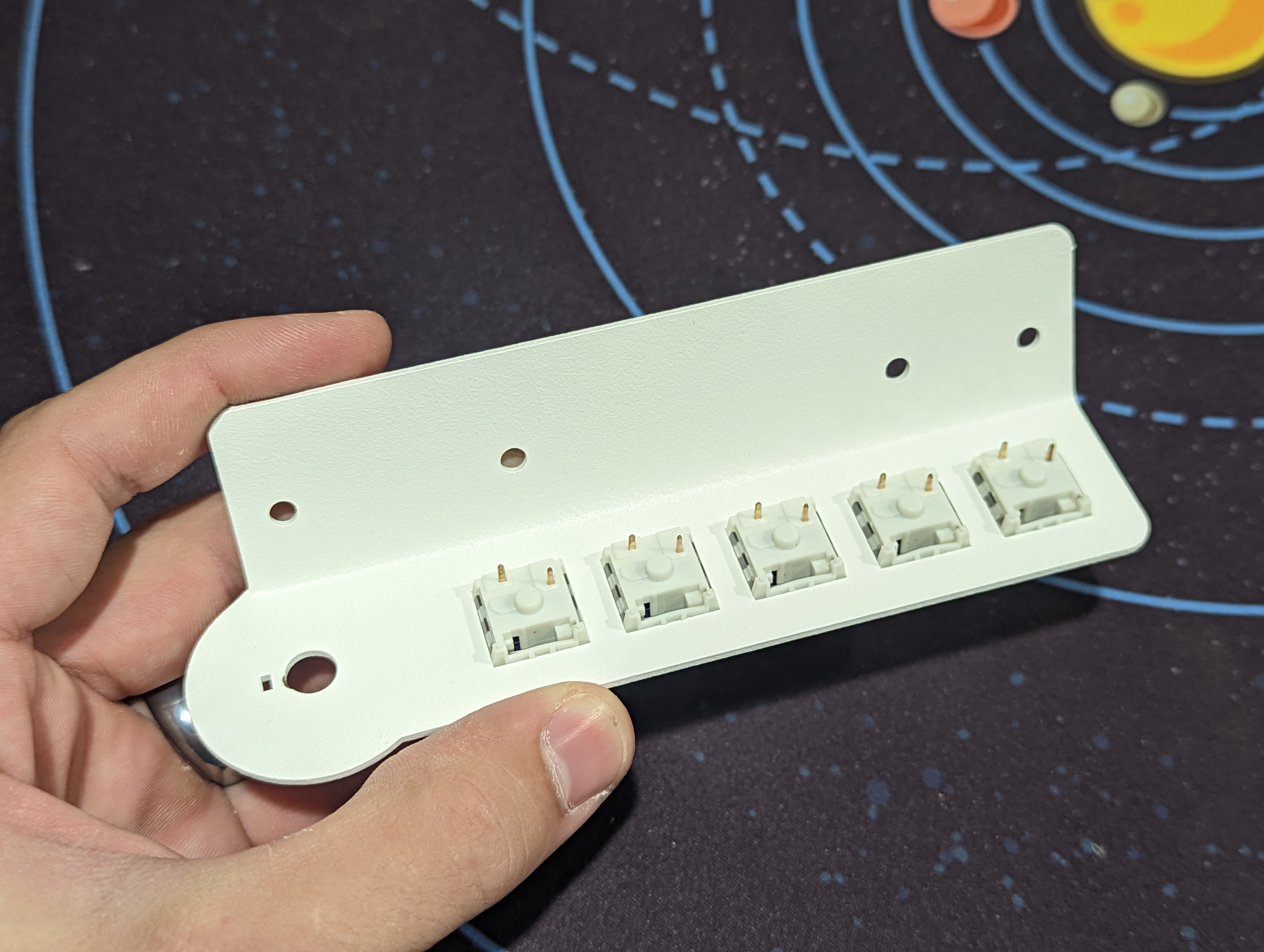
# Install the Mechanical Keyboard Switches
The mechanical keyboard switches need to be installed in a specific orientation. The LED slots face south or downwards when looking at the plate from the front. Make sure they snap into place and are flush with the top plate.
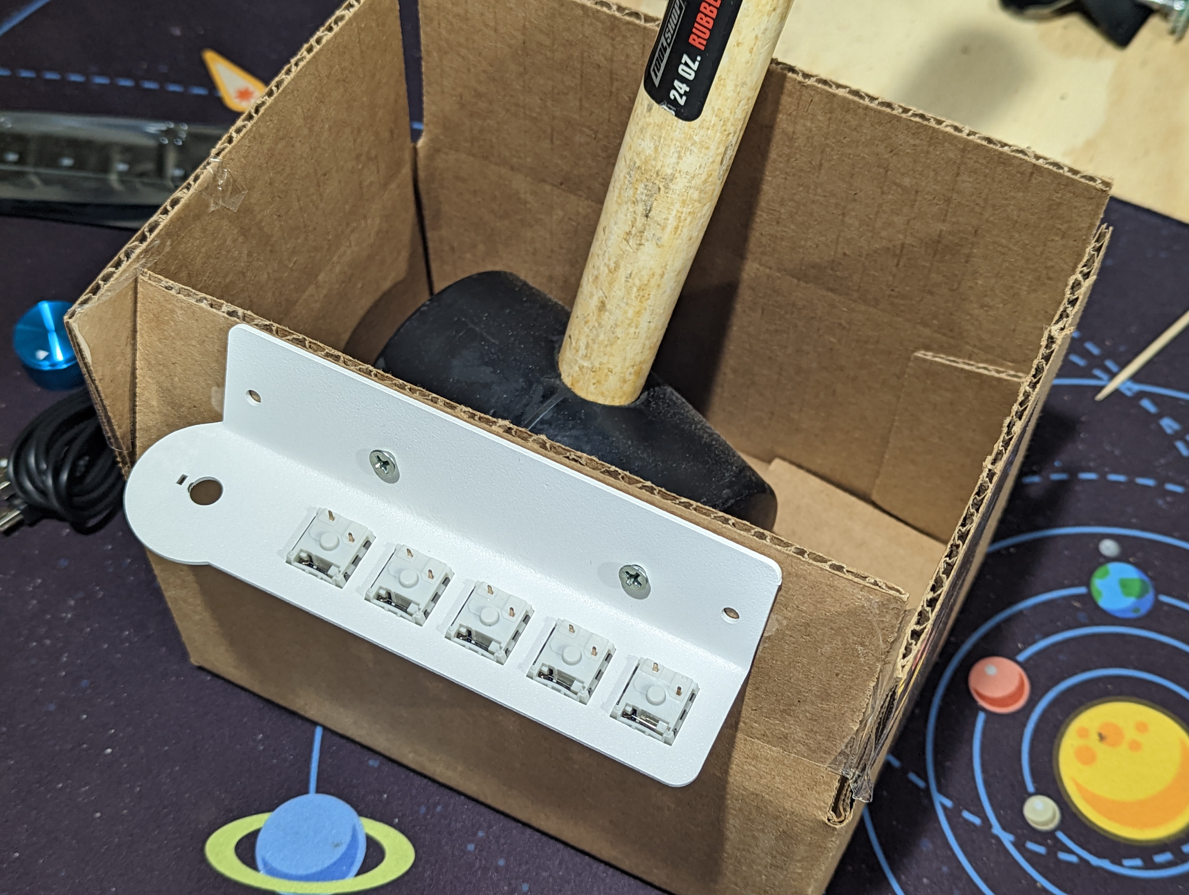
# Setup the Soldering Jig
Use a cardboard box (we recommend the box your kit came in) and tape one of the flaps so that it is at a 30 degree angle. Don't worry about this being precise or elegant, we are only using this to keep the macropad in the correct orientation for soldering without damaging the top plate surface.
Use the screws that were included in the kit for mounting to attach your macropad to your angled cardboard surface. Place something heavy in the box like a book or a mug to make sure it doesn't tip over while soldering.
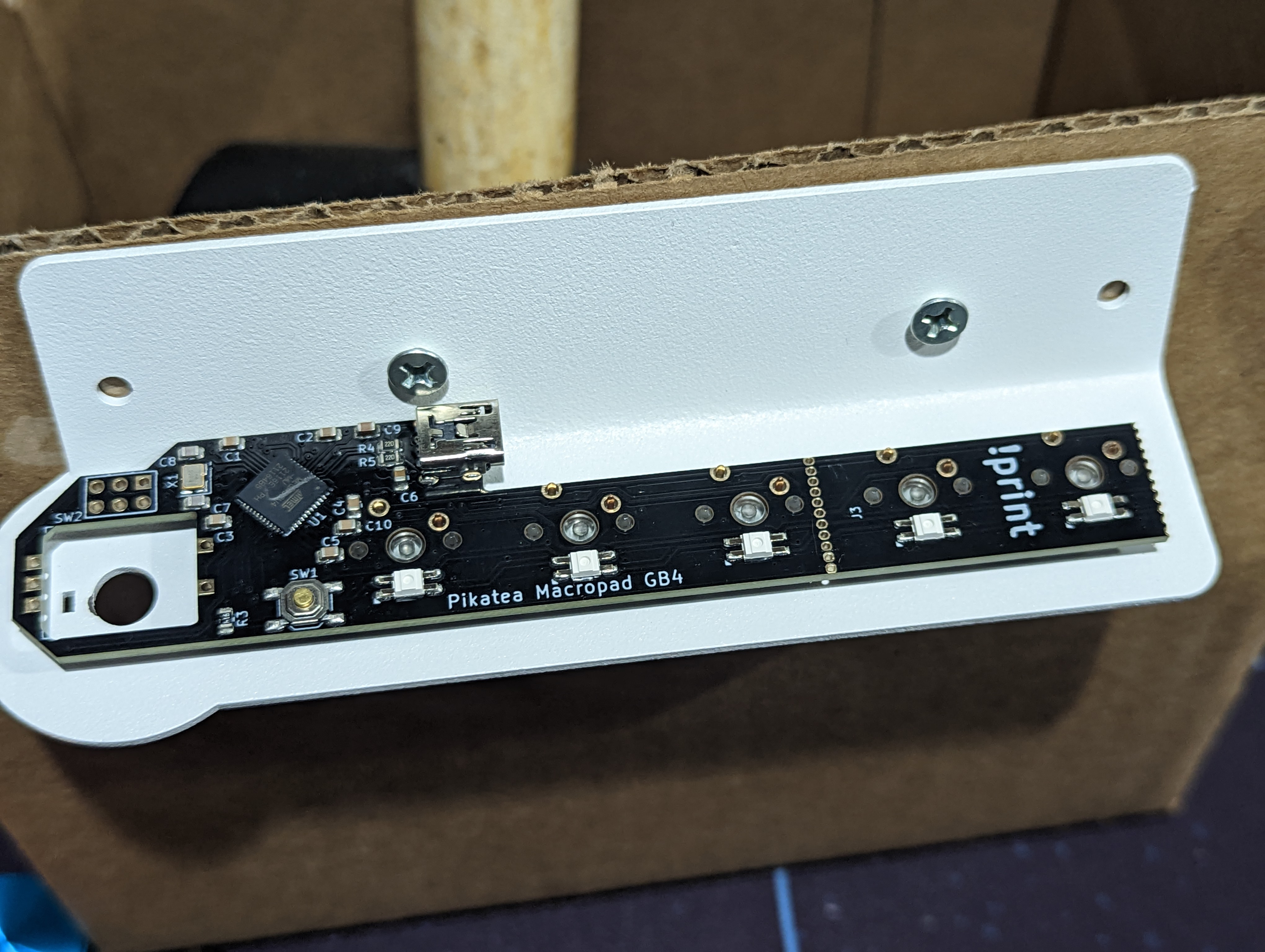
# Prepare the Circuit Board
The base circuit board is used for each of the 3 key, 5 key, and 7 key configurations.
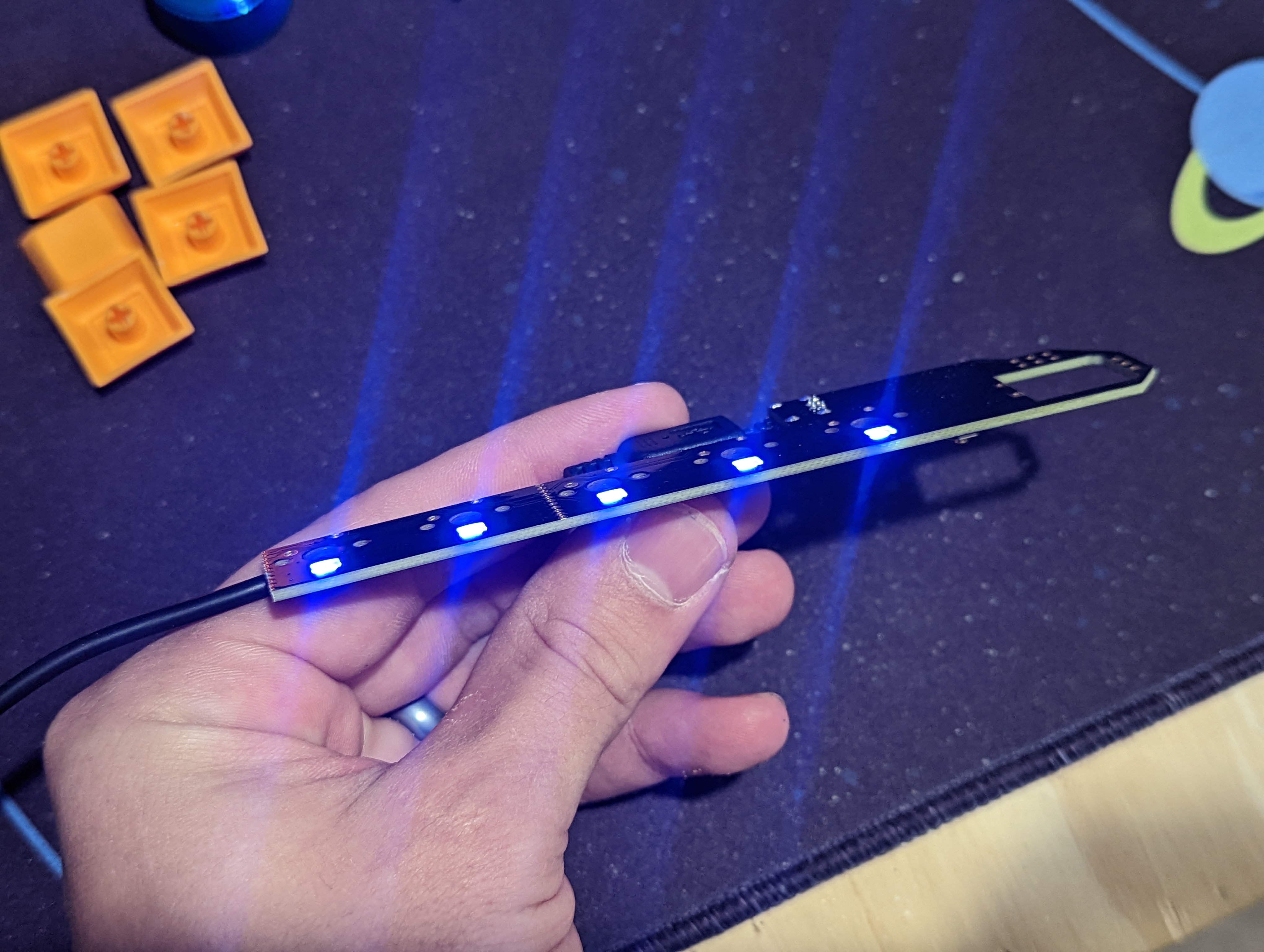
Plug in the PCB and verify all the LEDs work. Do this before snipping the board to the correct size.
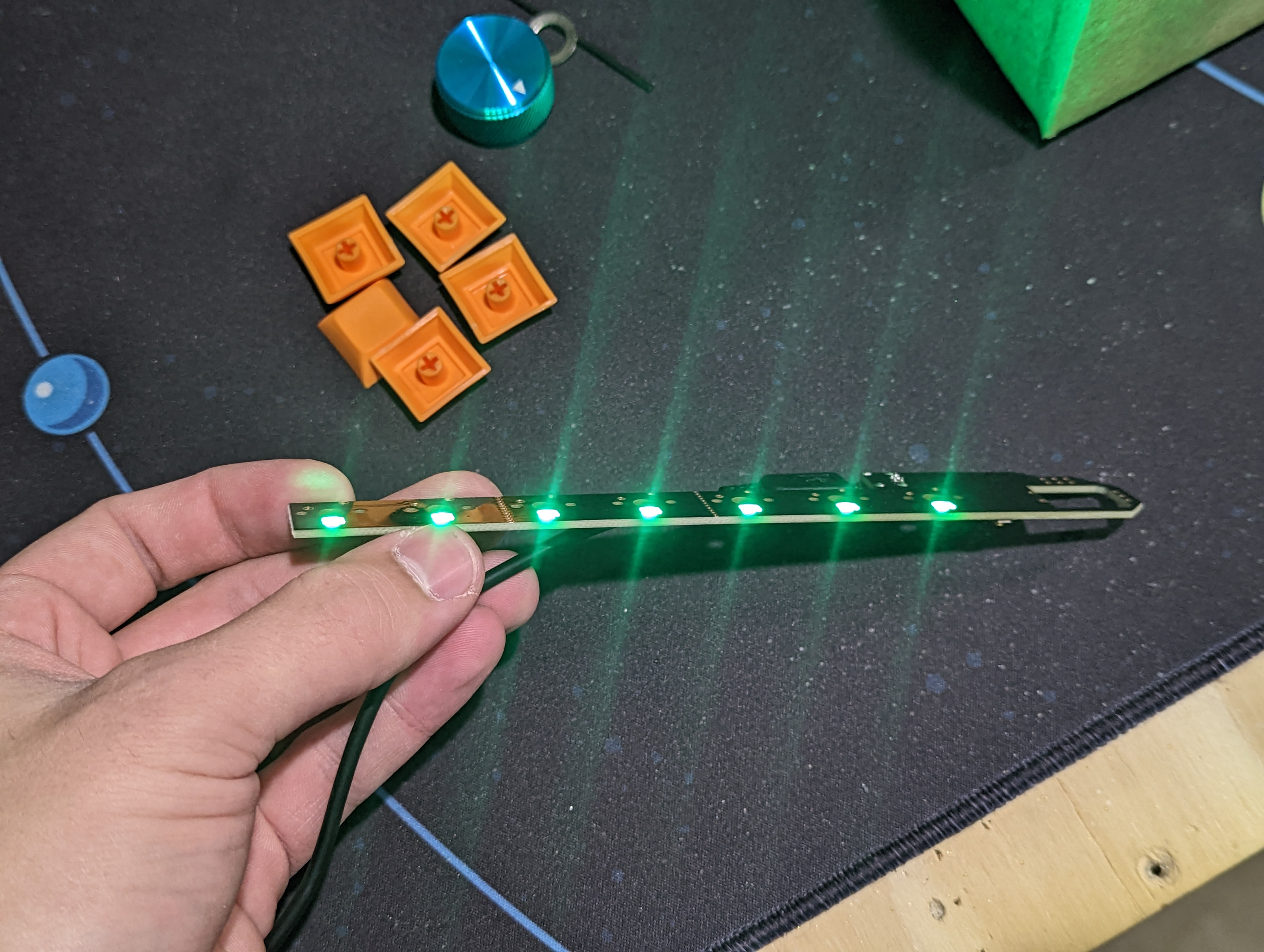
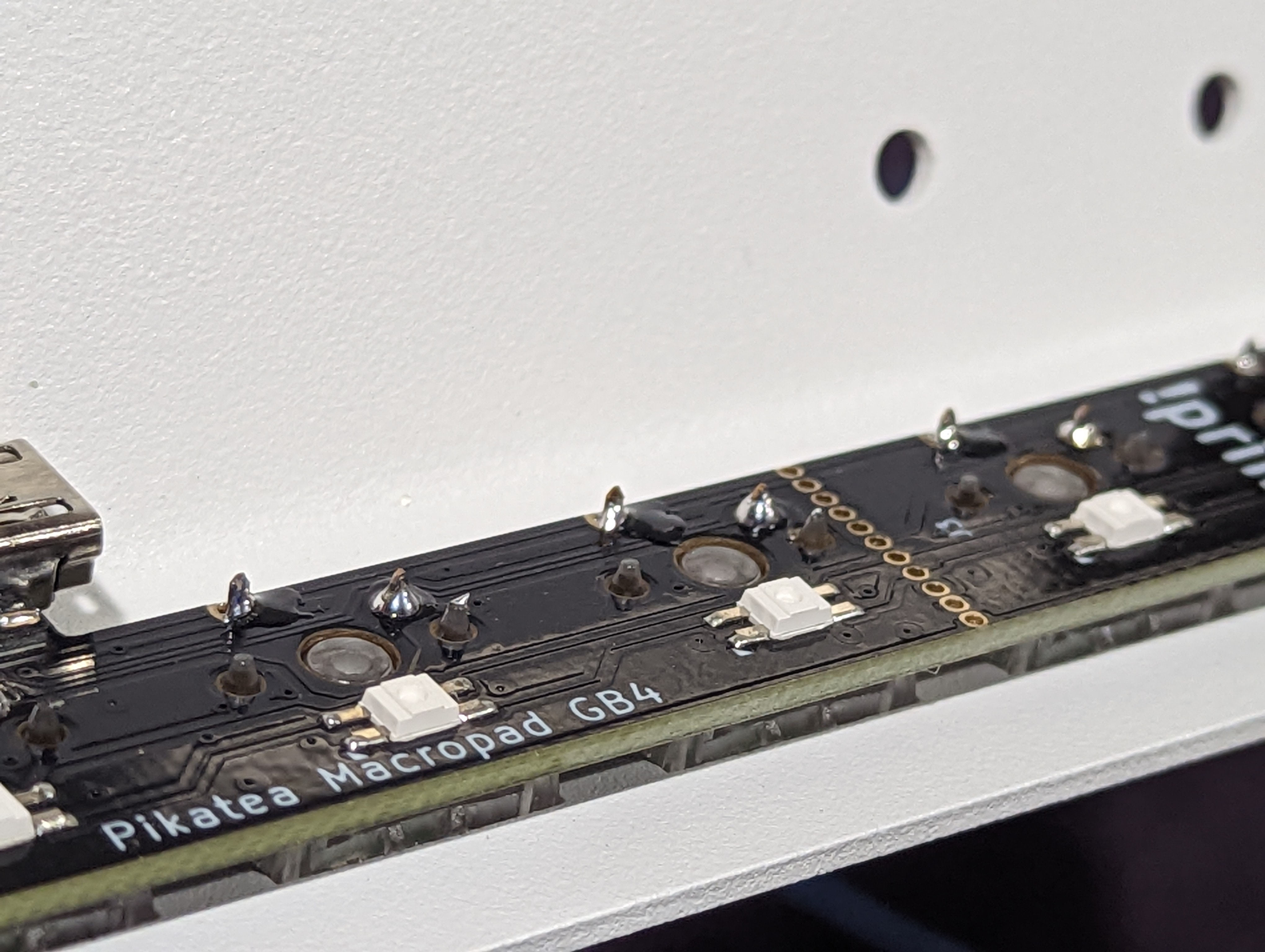
If you have a 3 Key or 5 Key configuration, you'll need to cut the PCB along the guided perforations. Use a pair of snips or wire cutters to cut the keys you need off the pcb.
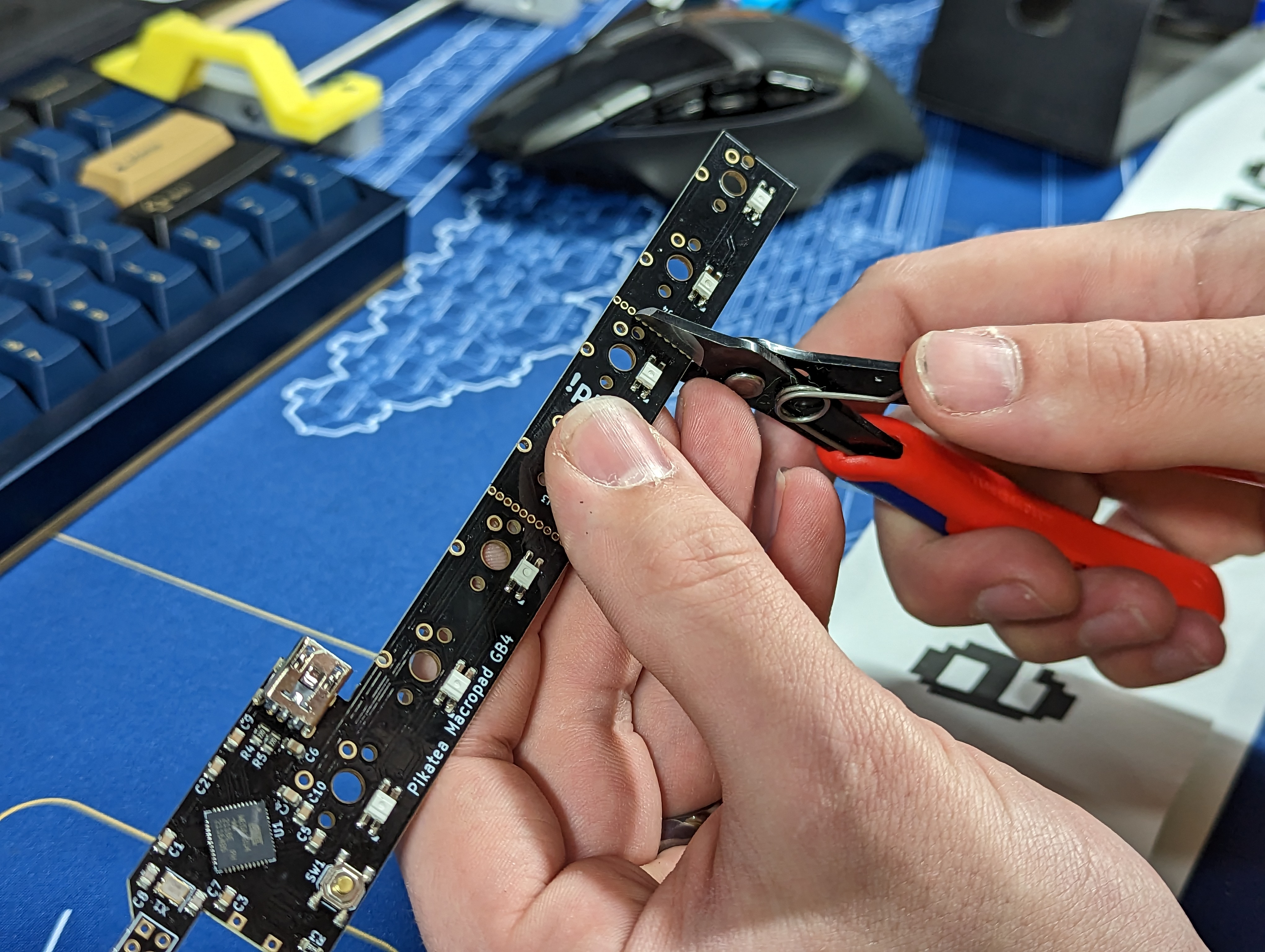
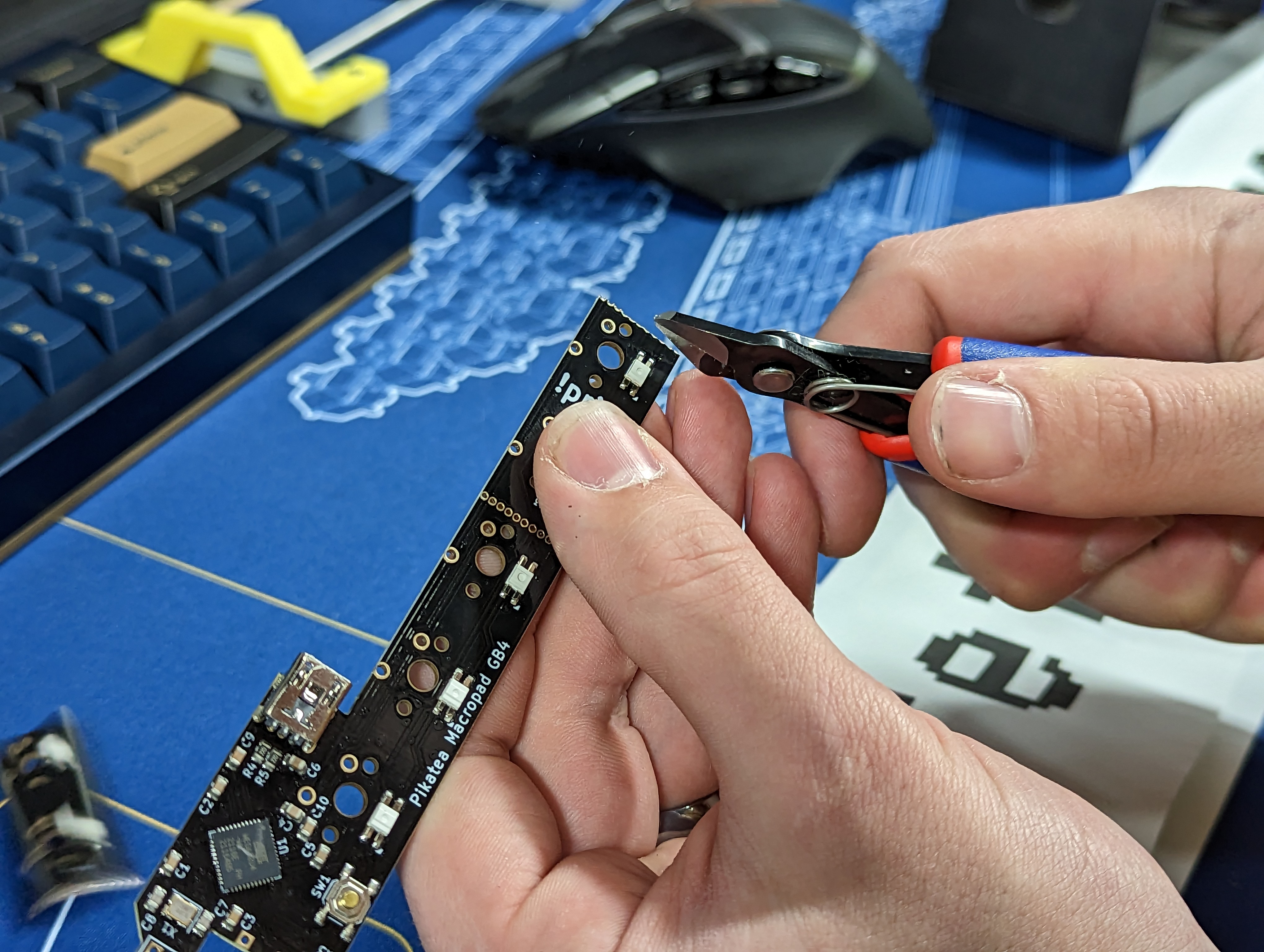
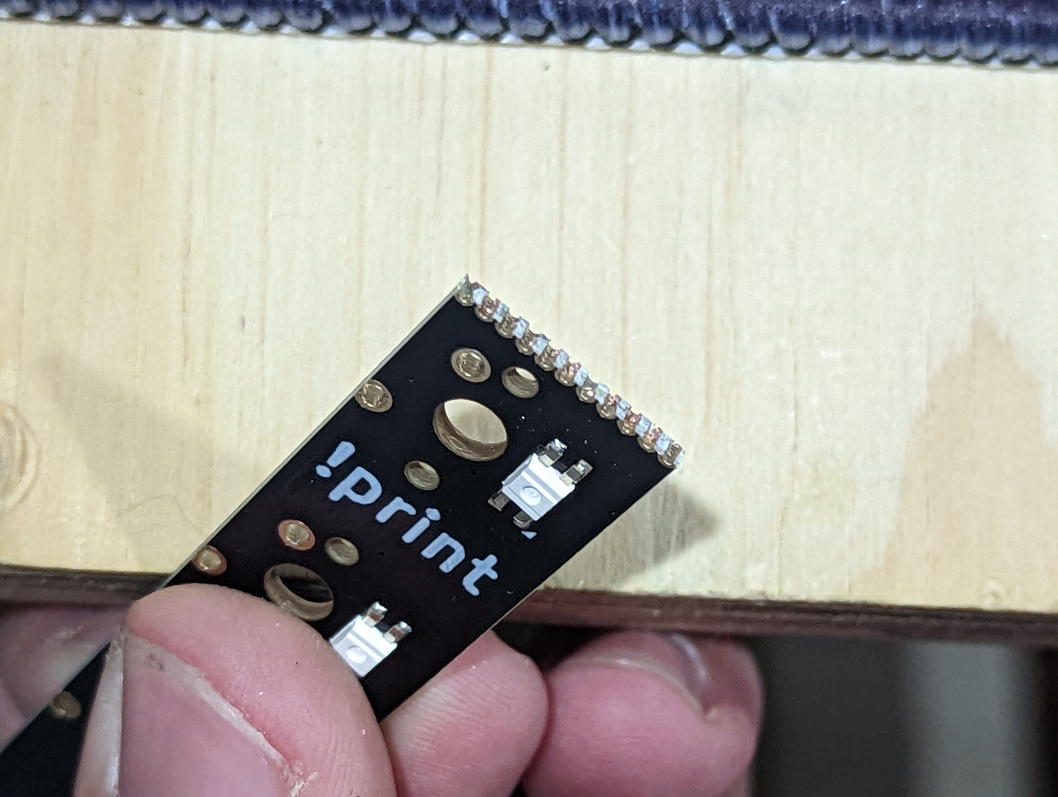
Clean up the edges of the PCB with scissors, sandpaper, and/or flush cuts so that the metal bits on the end do not touch each other causing an unexpected connection
Plug in the PCB and verify all the LEDs work again. Do this before soldering the switches!
Place the circuit board on the switches so the pins go through the holes. Some switches will require some extra force but most do not. Make sure everything is lined up and the pins are poking through. If not, you might have a bent pin.
# Solder the PCB to the switches
Solder the circuit board to the switches. Make sure to get them all!
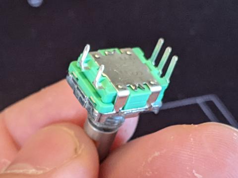
# Install the Rotary Encoder
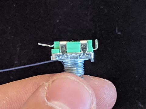
Next up is the rotary encoder. (Note: the encoder may already be prepped but here are the directions in case yours is not). Prep the rotary encoder by snipping the mounting tabs with snips or wire cutters. Cut the set of 3 pins shorter so they are flush with the bottom of the rotary encoder. Lastly, bend the set of 2 pins so they are pointing straight out with a slight angle.
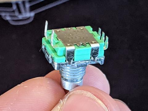
Place the rotary encoder in the hole of the top plate and hand tighten the washer and nut to hold it in place for soldering. Don't tighten this with any tools just yet. The washer has a slight bend in it so be careful to place the raised part in the center facing towards the front of the macropad. Use the pictures shown to ensure the correct orientation.
# Solder the Rotary Encoder
After the rotary encoder is in place, it is time to solder it. The 2 bent pins on the rotary encoder are resting just above the pads were they need to be soldered to, facing toward the switches. The 3 shorter pins on the rotary encoder are placed just to the side of the pads were they need to be soldered to. They do not go through the small holes. Take a look at the picture shown for a better explanation.

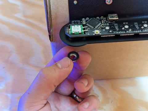
# Tighten the Encoder and Attach the Knob
Unscrew the macropad from the box but save it incase there is something wrong when testing.
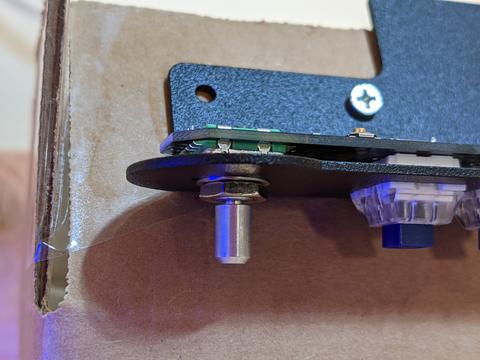
Tighten the encoder with a wrench, pliers or 10mm socket. Do not over tighten, especially if using a 3D printed top plate. Turning the nut about 1/4 of a full turn after hand tightening should fine for all plate materials.
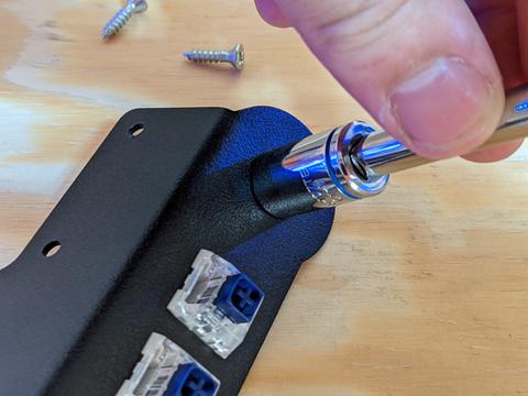
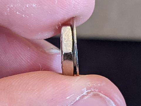
Use the Allen wrench included with the kit to bring the set screw inside the knob so that it barely pokes out. Place the knob on the encoder shaft so that the set screw interfaces with the flat part of the encoder shaft. After it is in place, tighten the set screw. Be careful not to over tighten with the 3D printed knobs or it will strip. Error on the side of too loose since it can be tightened later.


# Add the Keycaps
Add the keycaps to your macropad and click the switches a bunch because it's fun and satisfying.
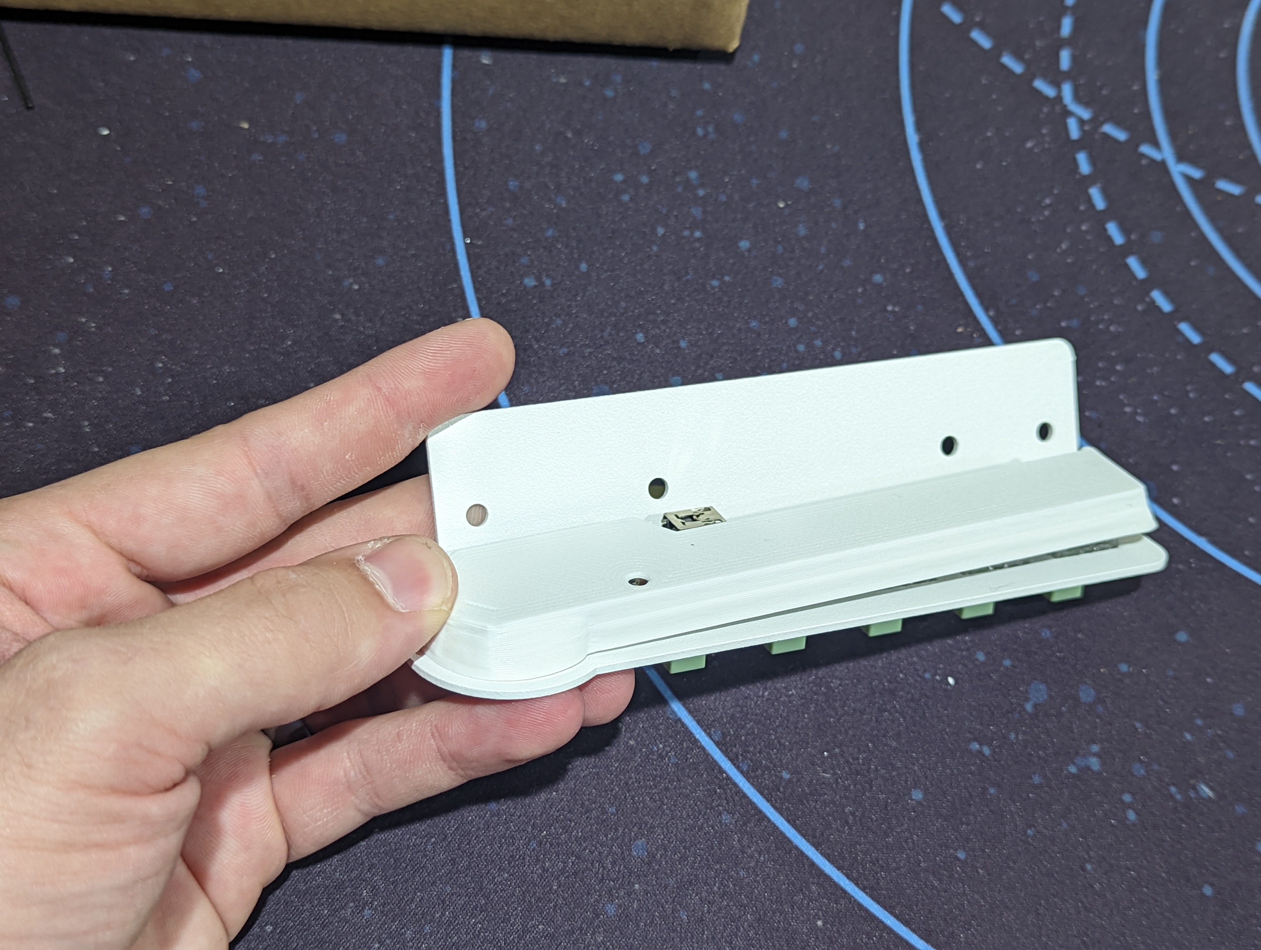
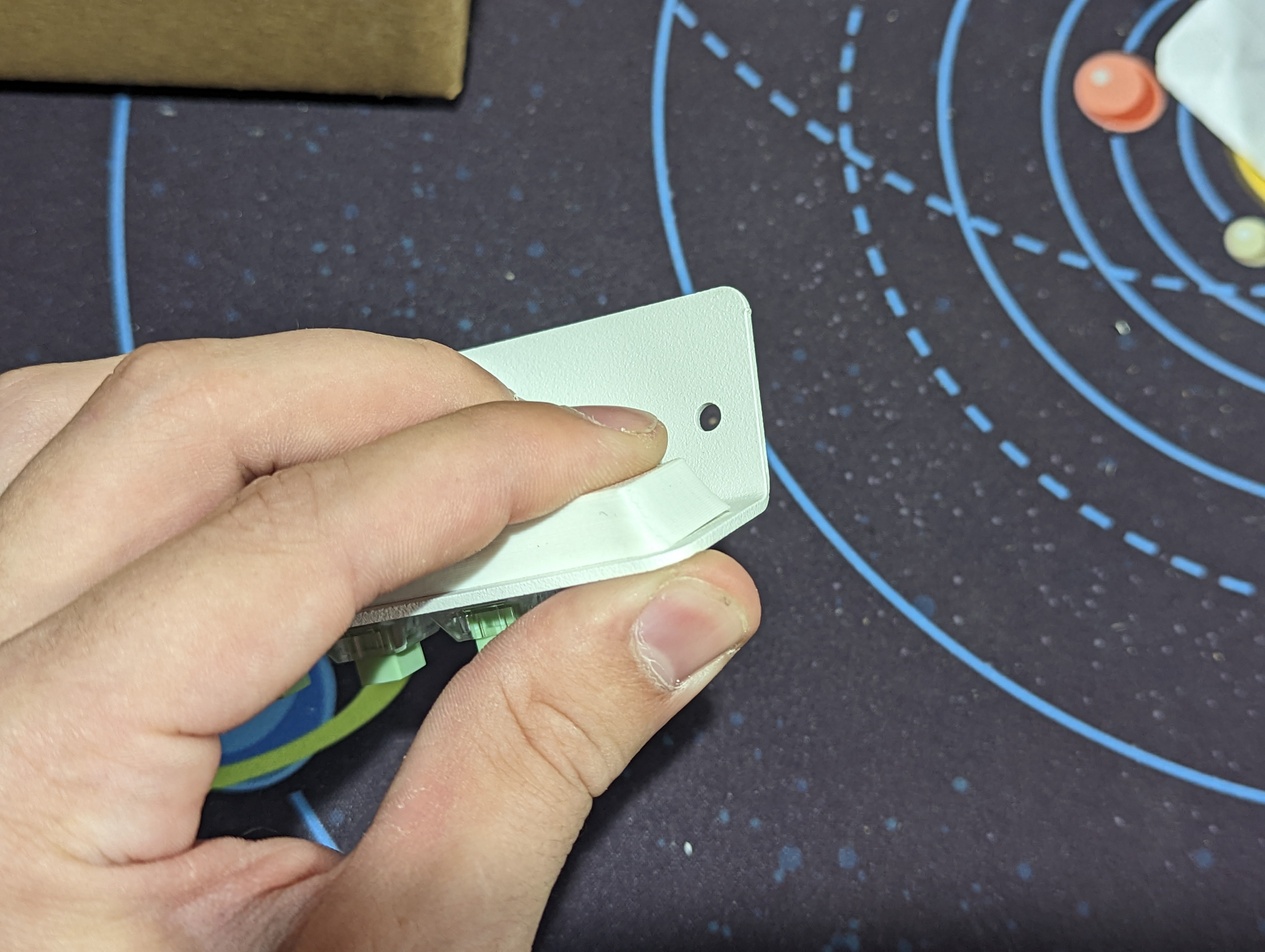
# Add the Backside Cover
Attach the included backside cover to the back. This is extremely important the pins are very sharp and you may accidently cut yourself when unplugging the cable. Again, you should definitely do this.
# Test the Macropad BEFORE mounting
This is a very crucial step. The last thing you'd want to do is install your macropad only to realize you forgot to solder all the pins correctly.
Follow the programming guide but mount the device later after you've verified everything functions.
If everything works, Congrats! You did it!
# Troubleshooting
Please ask on discord or email support if you have any other issues in regards to the assembly process.