# Parametric Series Assembly Guide (Rectangle with MX switch)
# NOTE This guide is a work in progress
# Flash the MCU
It's important to flash the MCU before starting to make sure it works.
- Download the .uf2 file for the device from the firmware list.
- While holding the boot button, plug the MCU into the computer.
- Drag the .uf2 file into the new drive that shows up. Confirm the device shows up in VIAL after it disconnects and reconnects.
TODO(add photos)
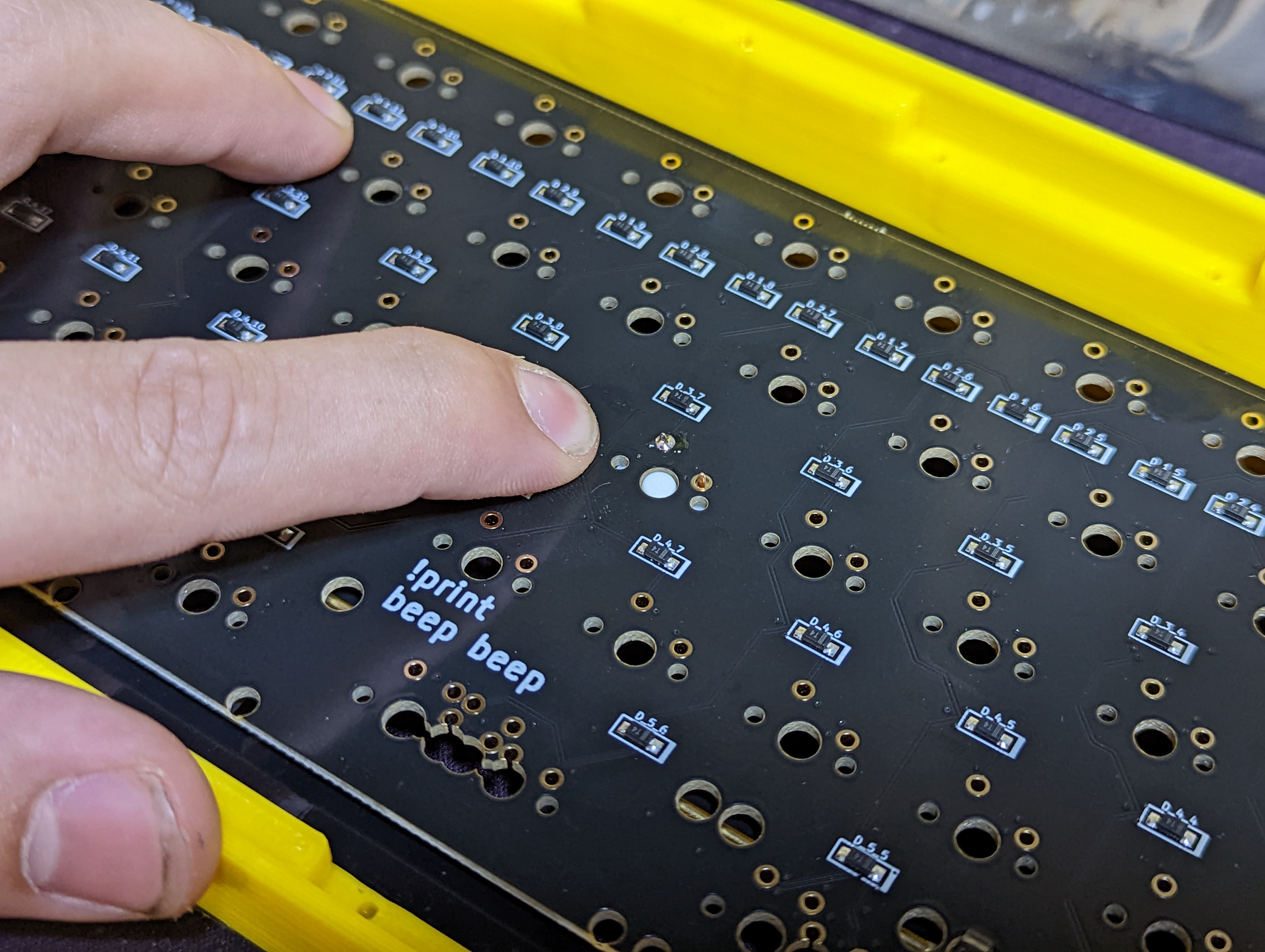
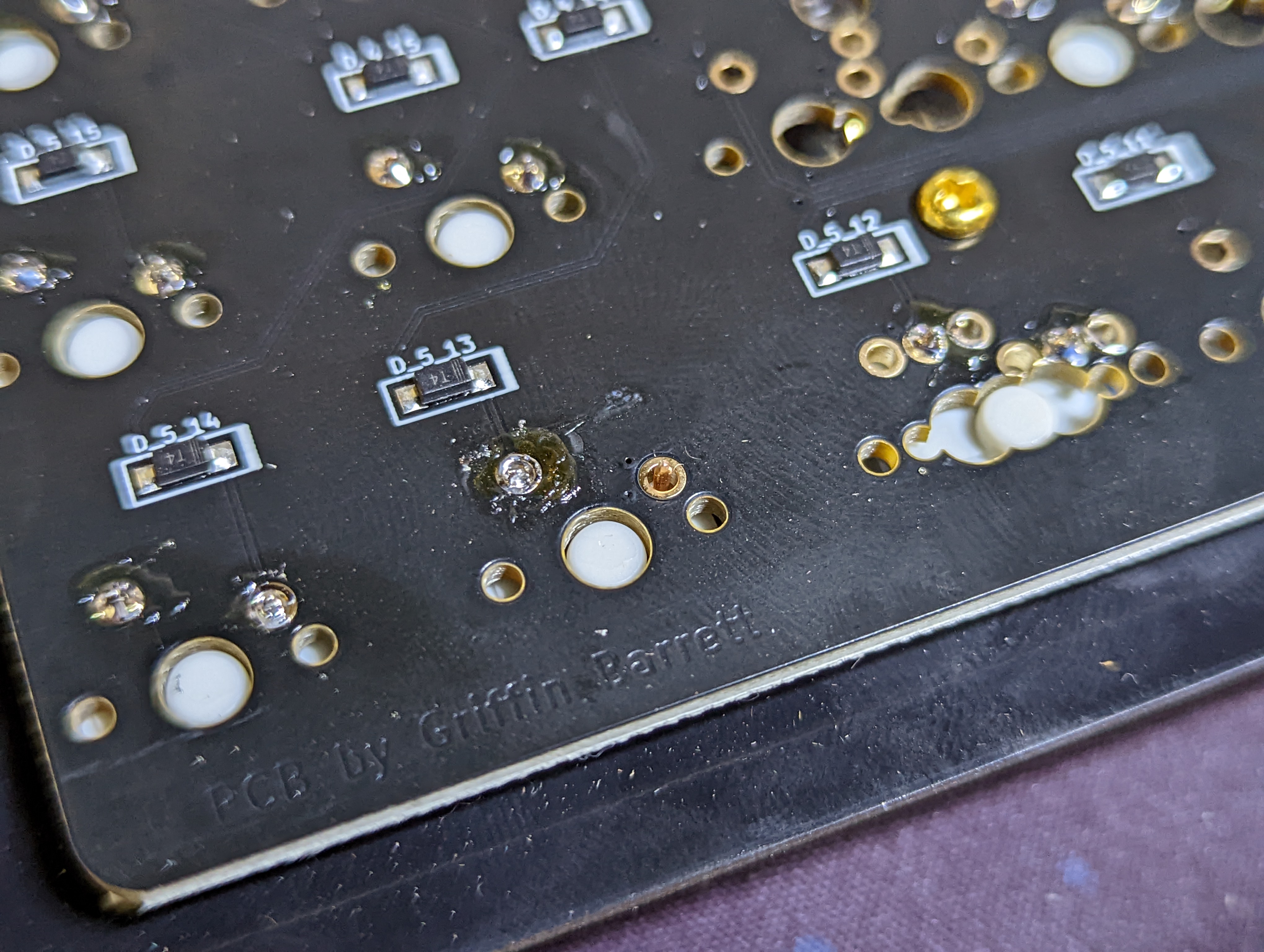
# Solder the Diodes
- Bend a diode and insert it into the PCB being careful it is the correct orientation. The black bar on the diode matches with the thicker white bar on the PCB.


- After the diode is inserted, bend the leads outwards so it stays in place. Repeat steps 1 and 2 for each diode.
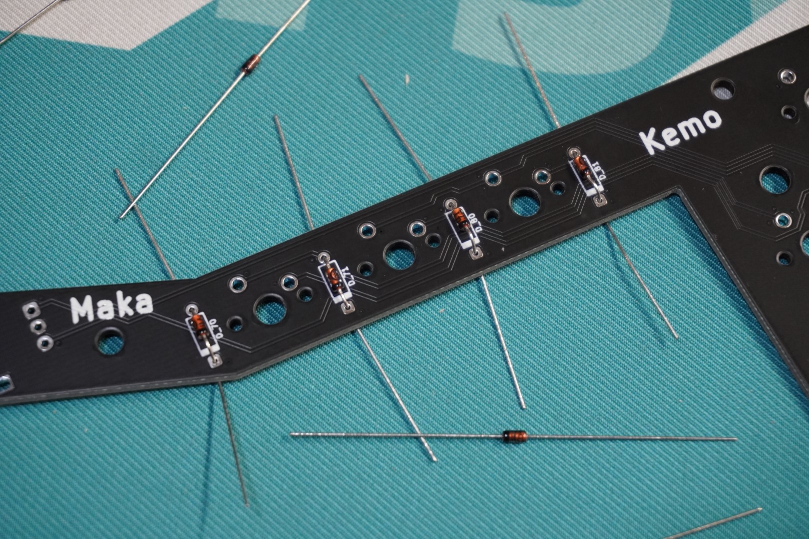
- With each diode in place, Solder them to be permanently secured.

- Bend the diodes legs straight and use flush cuts to them off. Be careful not to scratch the PCB when doing this.


# Solder Hotswap Sockets
- If any come with your kit, you'll need to solder them now. Most keyboards will at least have a few hotswap sockets that go under the MCU.


# Stabilizers
- Install the PCB mounted stabilizers.
They usually screw in but some might clip in. Below are a few links that explain keyboard stabilizers and how to install them. You'll need a stabilizer for each key that is 2u or larger.
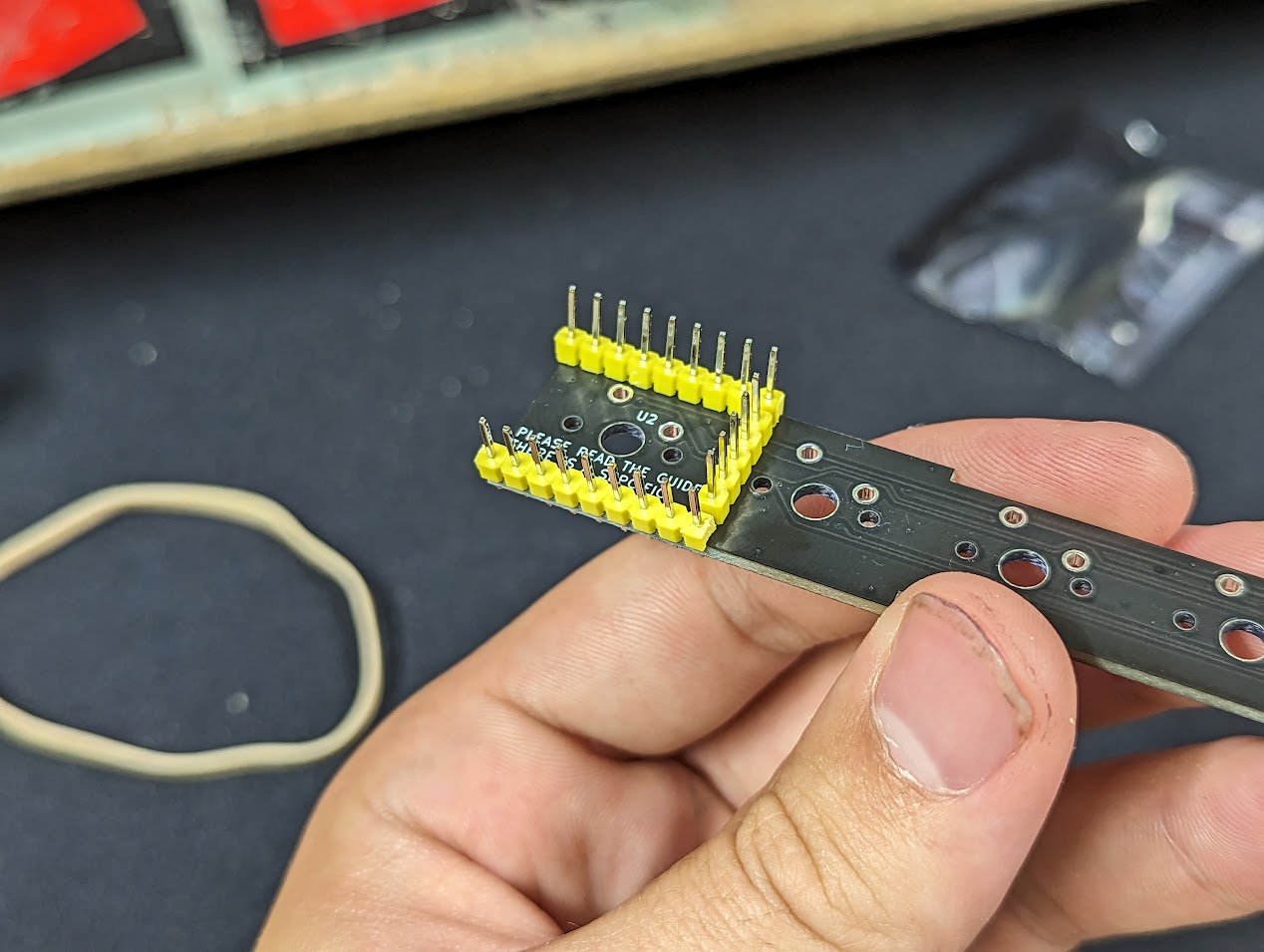
# Trim The Headers
The headers might need to be trimmed or the backplate will not fit. This is especially true for keyboards that have less than 4 rows. We recommend always trimming them. (Different boards will have different MCUs which will have different amounts of headers.)
- Cut the longer side of the headers in half as shown. It doesn't have to be precise.


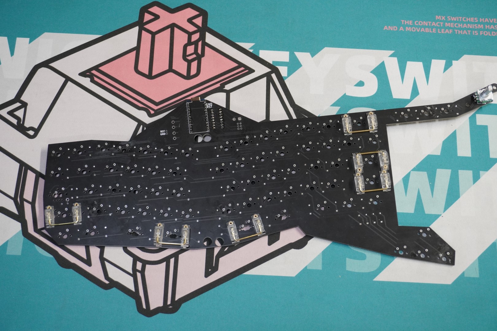
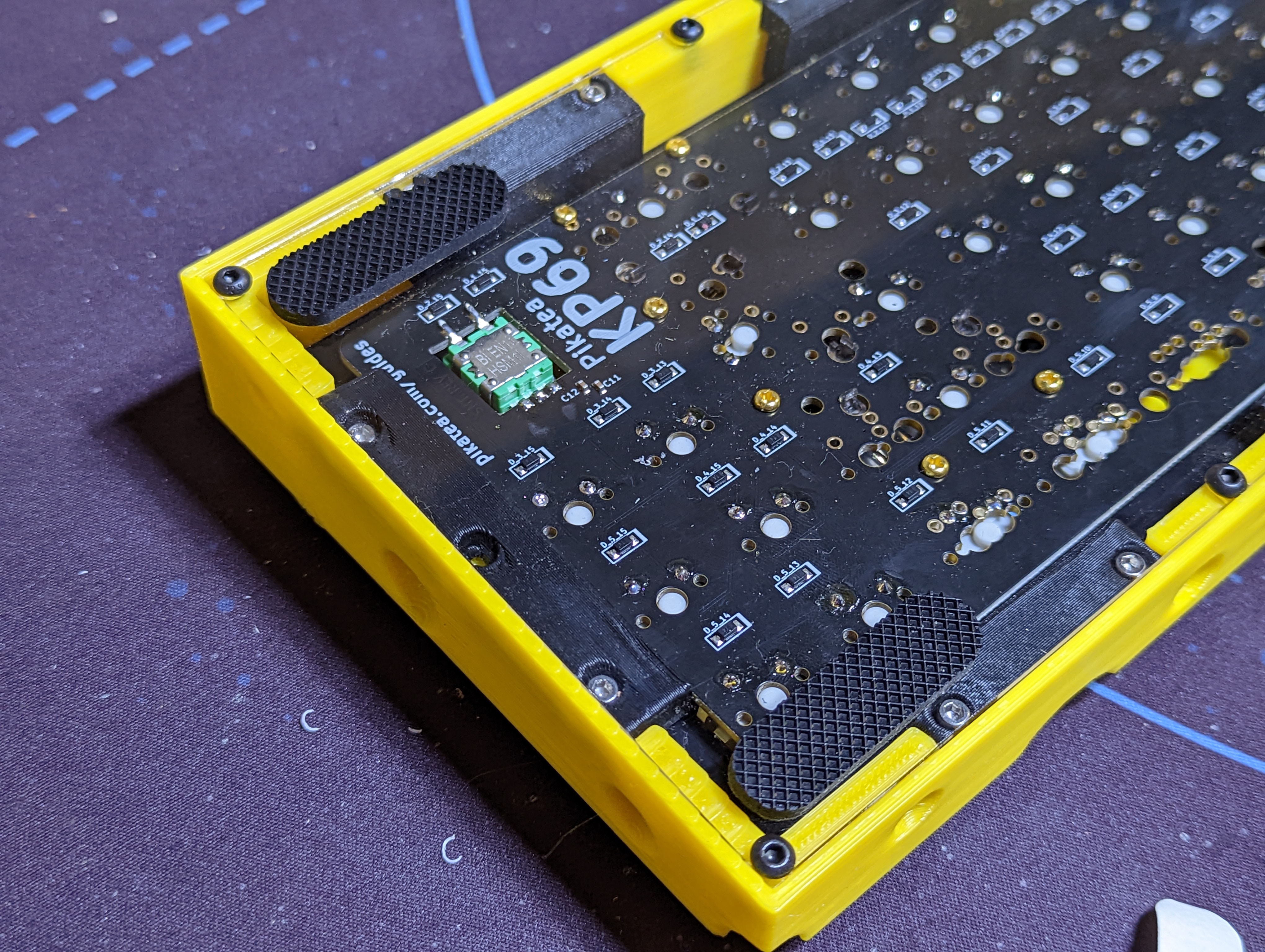
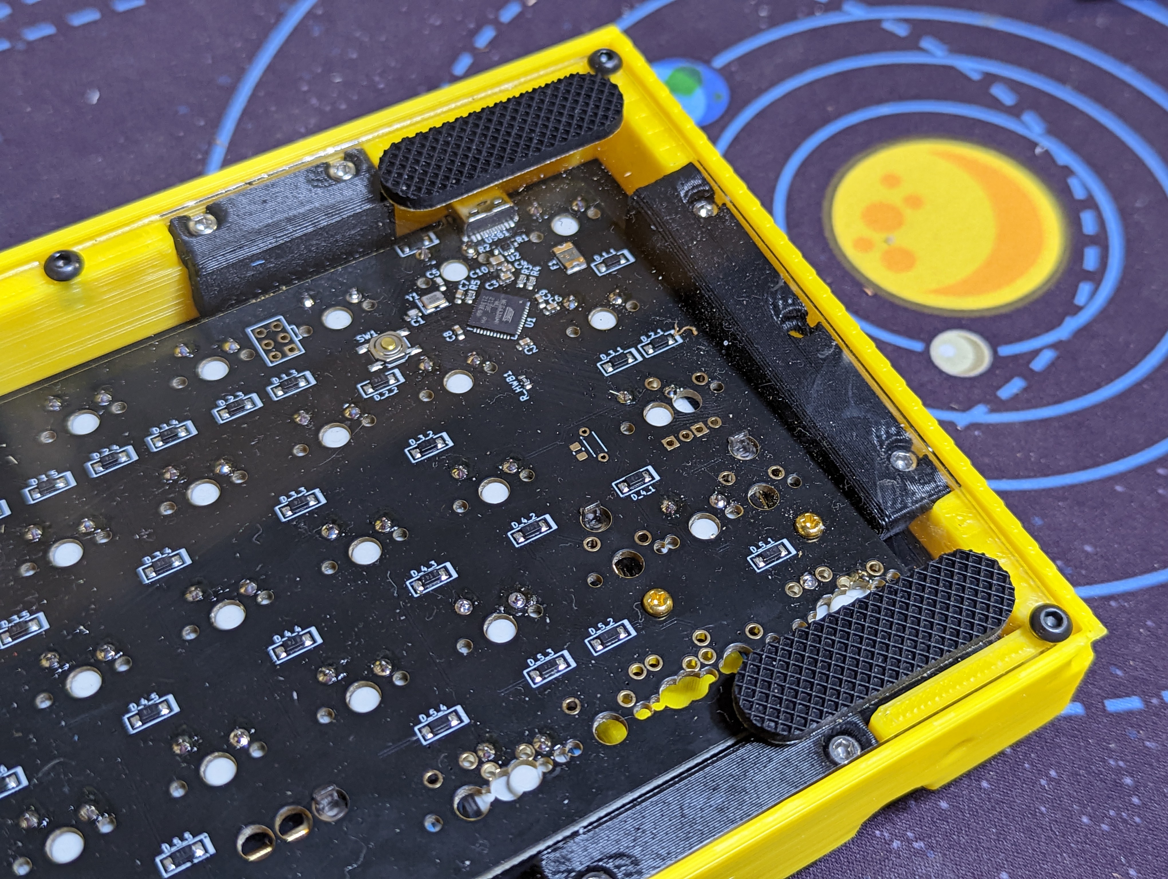
# Check for Soldered/Hotswap switches under the MCU
Check to see if there are switches that need to be soldered under the MCU. (Most designs will use hotswap sockets)
Example of soldered switches under MCU.
Example of hotswap switches under MCU.
If your keyboard kit contains soldered switches under the MCU, it's extremely important to follow a specific order. We also recommend converting them to hotswap with Mil-Max Sockets. Once a switch is soldered, it cannot be removed because the MCU will be covering it (We do our best to avoid this senario but it may be necessary because of design constraints. It's important to double check). Follow the step order outlined in The Richard Guide (v1)
If your keyboard kit contains hotswap sockets under the MCU, proceed with this guide as outlined.
# Solder MCU
- Insert the trimmed headers into the PCB.

- Add the MCU on top.


- Use a rubber band to hold everything in place.

- Solder both sides of the headers to perminently hold everything together.

# OLED
TODO (install the OLED at this point)1
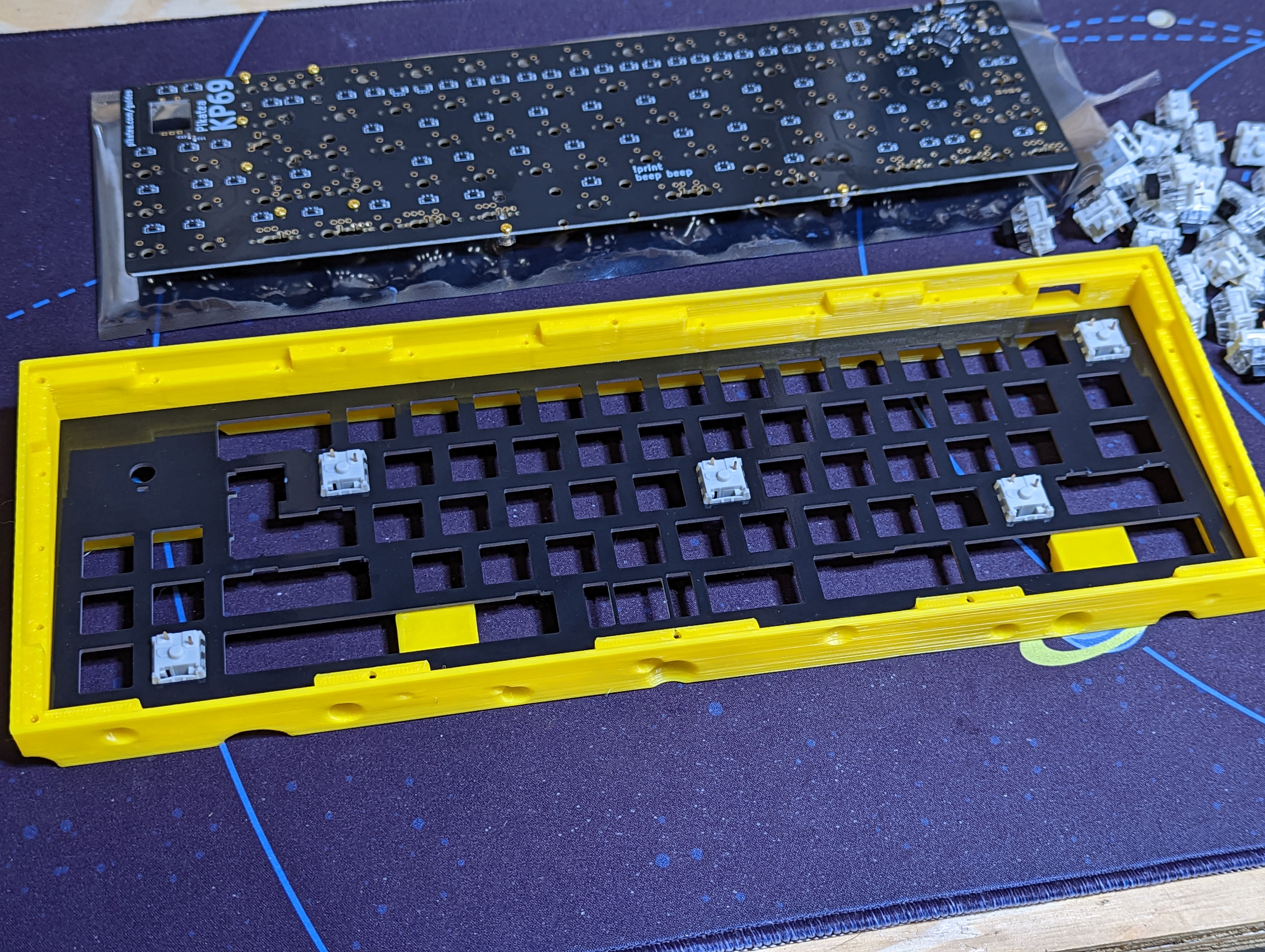
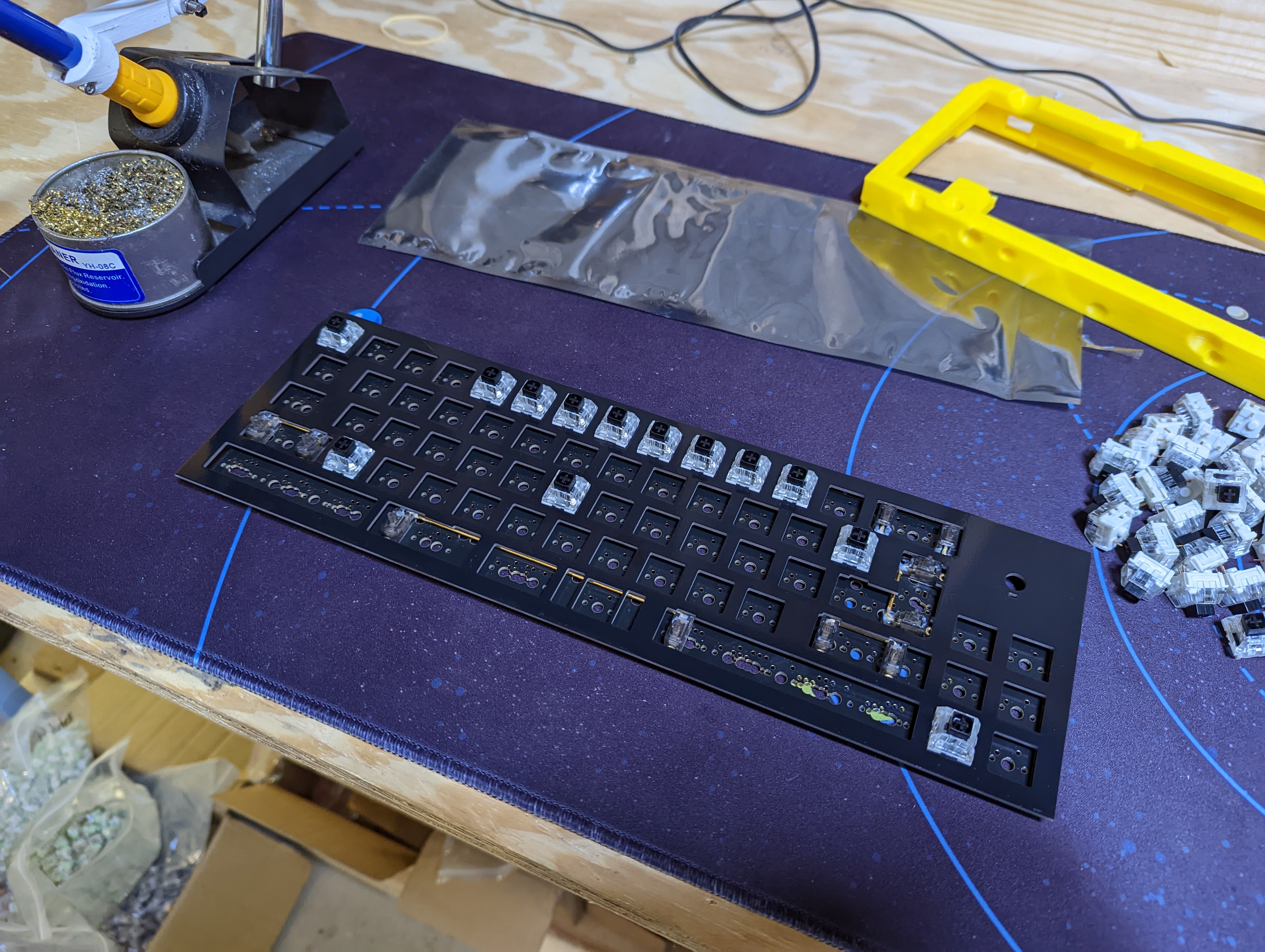
# Switches and Plate
The switches and the plate steps go together. It's your preference on the exact way to do it. If you're new to assembling keyboards, we recommend trying the order outlined
- Install a few switches into the plate.
- Install the plate and switches on the PCB, solder one lead of each switch if it's a soldered board.
Verify switches are sitting flush.
Insert the remaining switches into the plate.
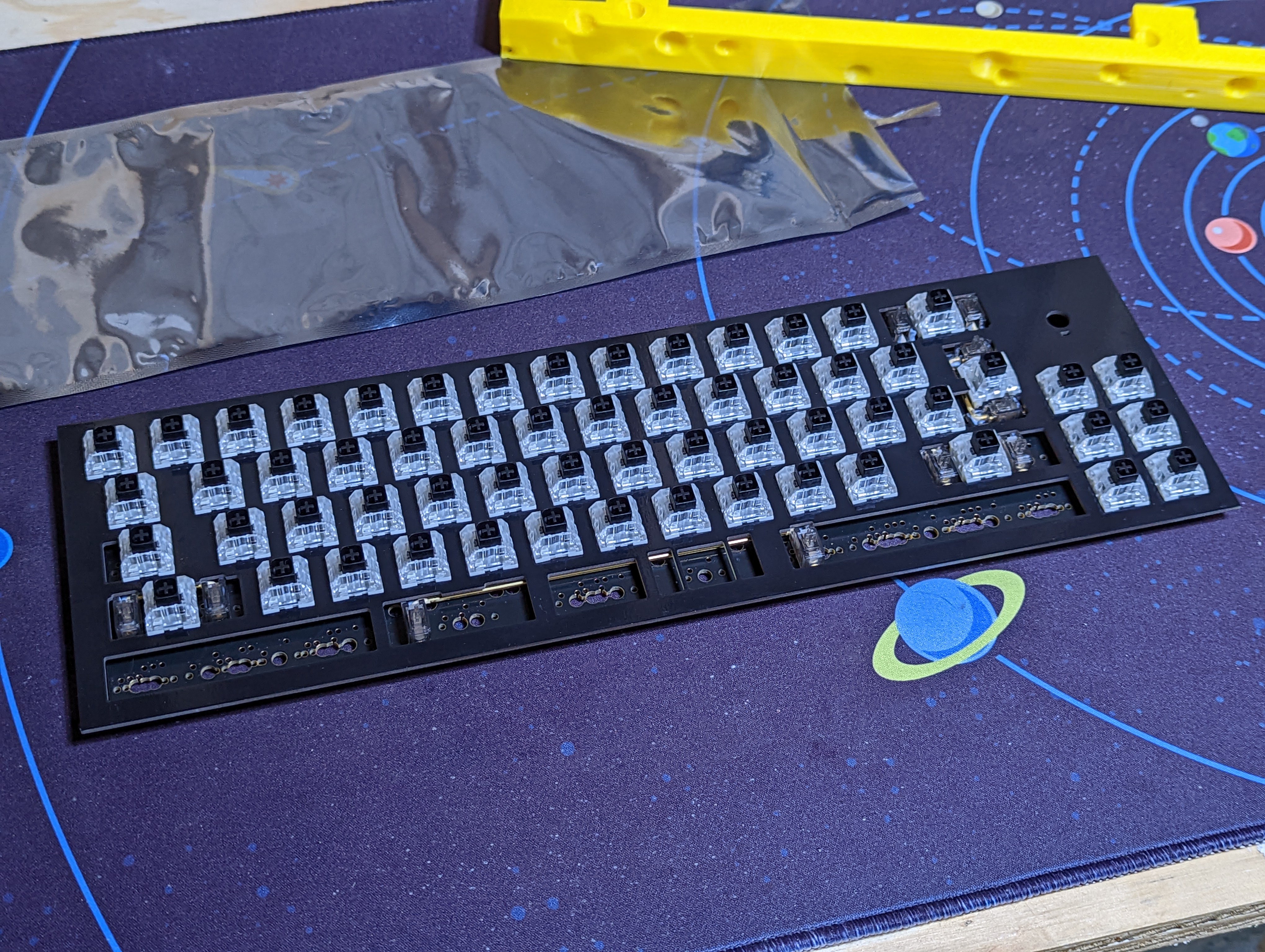
- finish soldering all the remaining switches.

# Rotary Encoders
WIP install rotary encoders
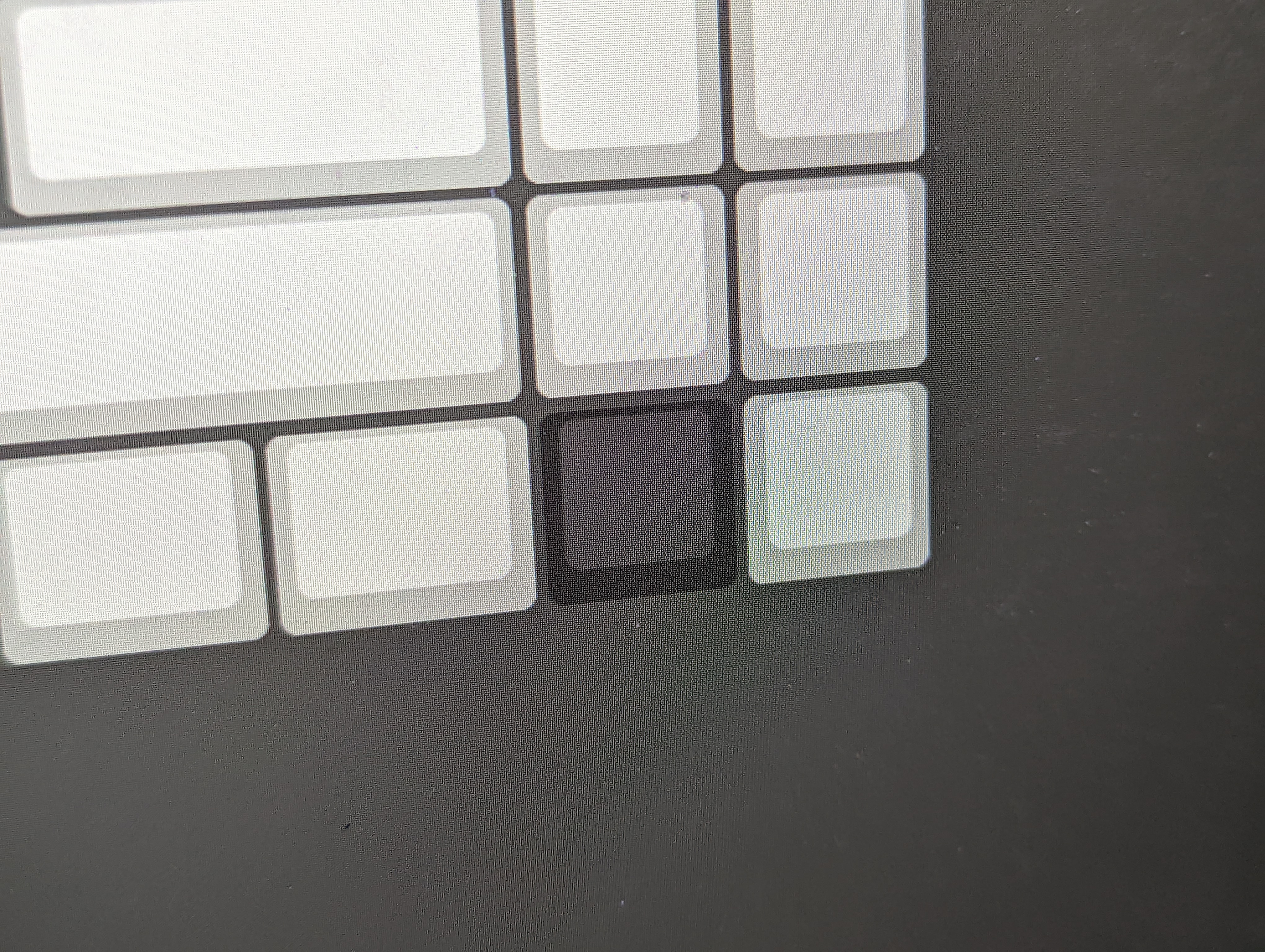
# Test the PCB
- Plug the finished MCU into the computer and open VIAL. Verify that each switch works by using the matrix tester in VIAL.
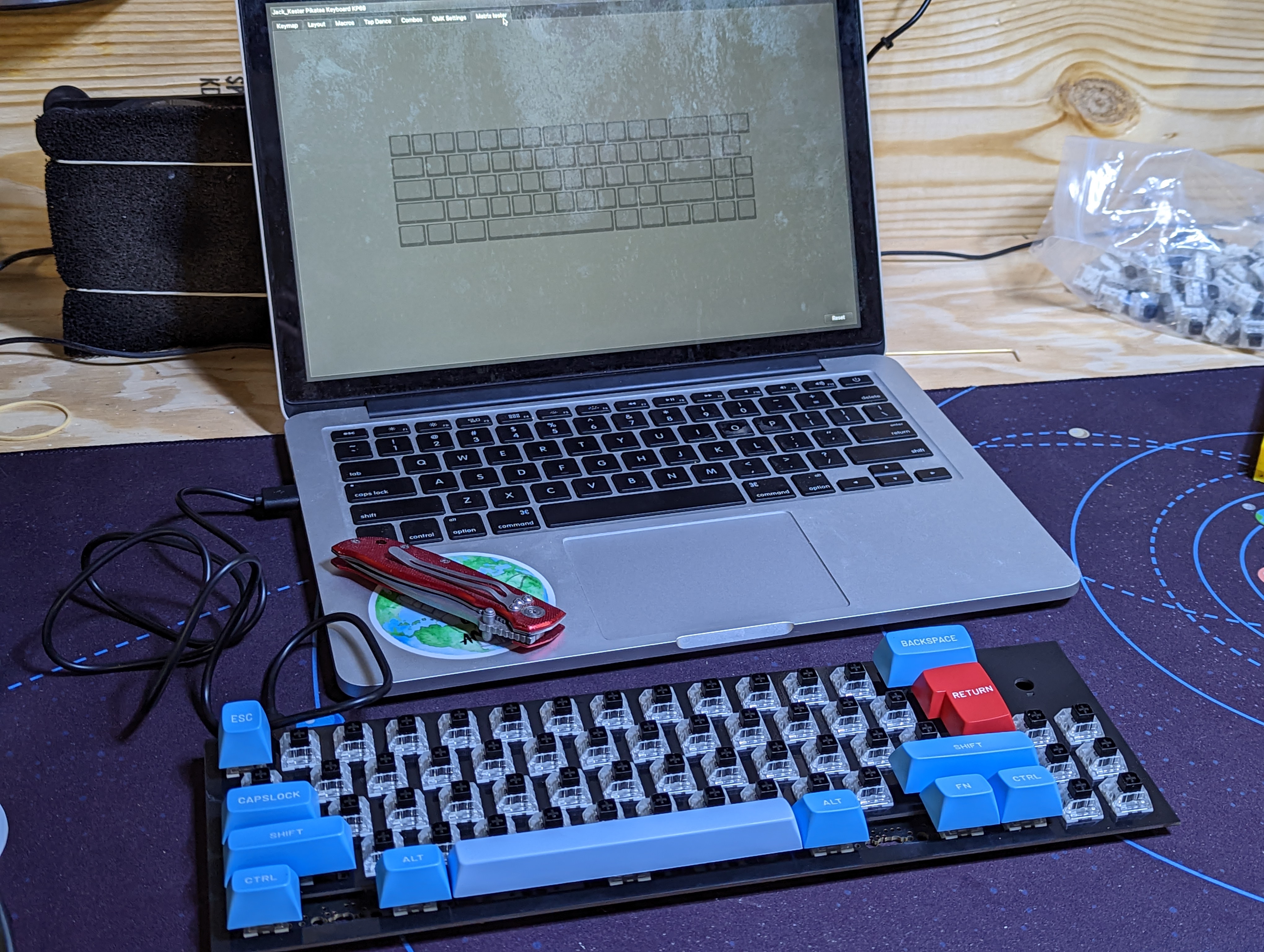
oops I missed a switch!
# Finish Assembly
With the PCB and plate put together, it's time to assemble the remaining components and complete the keyboard.
- Insert square nuts into the "Top" peice of the case. You may have to use a small allen key or other sturdy object to push them into place.
(TODO add images)
- Place the Plate and PCB assembly into the "Bottom" piece of the case.
(TODO add images)
- Place the "Top" peice onto the "Bottom" peice. If notch on the inside of the "Top" piece goes in the left of the keyboard. This is important because the "Top" peice is not symetrical top to bottom.
(TODO add images)
- Insert the M3x10mm in the front holes and M3x20mm or M3x25mm, whichever is included, into the the back holes. Tightenm them down pretty good with an allen wrench.
(TODO add images)
# Add Keyboard Feet
# Add keycaps and knobs
# That's it!
- Celebrate. It's required.
Check out the programming guide to learn more about how to use your device.